Machine and method for fitting and removing a tyre

a technology of tyres and machines, applied in the field of machines and methods for fitting and removing tyres, can solve the problems of increasing production and maintenance costs, affecting the freedom of movement of operators, and increasing the dimensions of tyre changer machines, so as to reduce the possibility of errors, facilitate pushing action, and increase the reliability of machines.

Active Publication Date: 2016-01-07
NEXION SPA
View PDF2 Cites 15 Cited by
  • Summary
  • Abstract
  • Description
  • Claims
  • Application Information

AI Technical Summary

Benefits of technology

[0046]Moreover, preferably, the wall pressing tool is positioned at a greater distance from the upper operating head than the upper fitting tool, in the direction of the first axis of rotation of the wheel-holder unit (that is, of the longitudinal axis of the upper fitting tool). This facilitates a pushing action on the side of the tyre when the upper fitting tool is positioned for operating between bead and edge of the rim.
[0047]It should also be noted that the solution proposed by this invention increases the reliability of the machine, since it reduces the possibility of error by the operator by limiting the number of operations the operator needs to perform, for example, the manual positioning of the wall pressing tool in its operating position.

Problems solved by technology

The presence of many movement apparatuses limits the vision of the operator in the proximity of the zone in which the machine operates on the wheel, hindering the freedom of movement of the operator.
This also translates into a significant increase in the dimensions of the tyre changer machines, which have a rather complex structure.
The complexity of the machines increases the production and maintenance costs.
Moreover, the increased complexity of these machines makes them more difficult to use by the operator to detriment of the reliability, thereby increasing the risks of error.
However, these tyre changer machines also have certain shortcomings, because they do not allow the tyre to be mounted in a particularly simple, reliable and comfortable fashion, with a particularly reduced number of actions by the tyre repair specialist.

Method used


Image

  • Machine and method for fitting and removing a tyre
  • Machine and method for fitting and removing a tyre
  • Machine and method for fitting and removing a tyre

Examples


Embodiment Construction

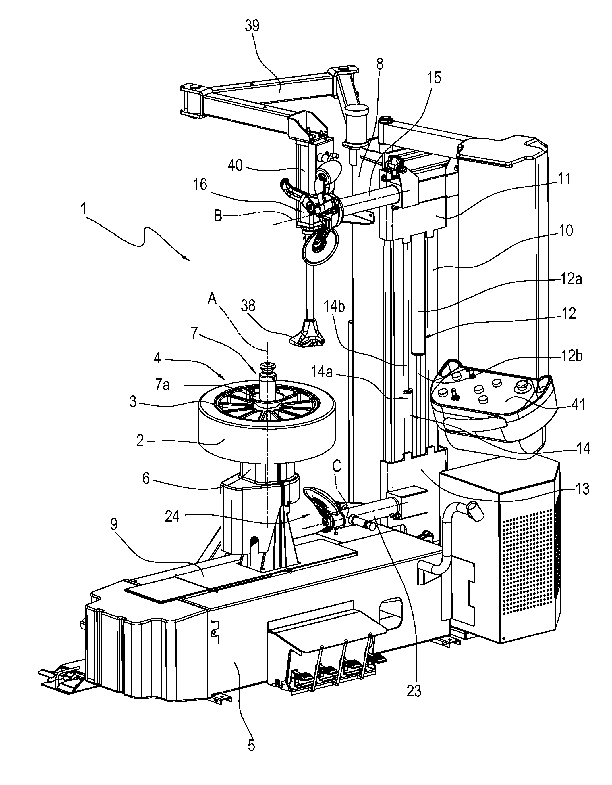
[0104]With reference to the accompanying drawings, the numeral 1 denotes a machine for fitting and removing a tyre 2 from a corresponding rim 3 of a wheel 4 (that is, a tyre changer machine) according to this invention.

[0105]The machine 1 comprises a base 5. The base 5 comprises a wheel-holder unit 6. The wheel-holder unit 6 is designed to house the wheel 4 and to rotate it about a first axis of rotation “A”, in order to allow the above-mentioned removing and fitting operations. Preferably, the first axis of rotation “A” is vertical.

[0106]The wheel-holder unit 6 comprises a hollow shaft, connected to rotation means (not shown), and a perforated supporting surface (not shown, of known type) to allow a clamping tool (or rod) 7 to pass through. Typically, the clamping rod 7 (of known type) is defined by a longitudinal shaft having a conical, intermediate or end, portion 7a, for the purpose of centring the wheel 4.

[0107]The wheel 4 is locked so as to rotate as one with the shaft of the ...


PUM

PropertyMeasurementUnit
angleaaaaaaaaaa
rotationaaaaaaaaaa
angleaaaaaaaaaa

Abstract

A machine (1) for fitting and removing a tyre (2) from a corresponding rim (3) of a wheel (4) of a vehicle, comprises: a rotating wheel-holder unit (6); a column (8); an upper arm (15) and a lower arm (23) slidably coupled to the column (8); an upper operating head (16); a lower operating head (24), rotating about a third axis of rotation (C) and equipped with a lower fitting tool (33), elongate in a direction for being operatively inserted between a lower bead of the tyre (2) and an upper edge of the rim (3) and angularly spaced from the lower bead breaker tool (32) by a predetermined angle, so that the tools are selectively and alternatively positionable in an operating configuration.

Description

BACKGROUND OF THE INVENTION[0001]This invention relates to a machine and a method for fitting and removing a tyre.[0002]To perform the removal of a tyre from a rim and the subsequent fitting operation, the state of the art consists of tyre changer machines having a wheel-holder unit and at least one operating unit.[0003]The wheel-holder unit is designed to support and rotate the wheel about an axis. The operating unit comprises the tools used in different operating steps which entail:[0004]detaching the bead of the tyre from the annular end (that is, edge) of the rim (process also known as bead breaking);[0005]removing the tyre from the rim, that is, removing the tyre from the housing defined by the space between the two annular edges of the rim;[0006]fitting a new tyre on the rim, that is, positioning a new tyre in the housing.[0007]It should be noted that the expression “tyre changer machine” is commonly understood to refer to a machine which is able to both remove the tyre from t...

Claims


Application Information

Patent Timeline
Patent Type & Authority Applications(United States)
IPC IPC(8): B60C25/138B60C25/05
CPCB60C25/138B60C25/0593B60C25/059B60C25/0512
Inventor CORGHI, GIULIO
Owner NEXION SPA
Why Eureka
Try Eureka