Separable distribution rotor and horizontal rotor distributor having the same

a technology of horizontal rotor and distribution rotor, which is applied in the direction of lighting and heating apparatus, combustion types, furnaces, etc., can solve the problems of difficult separation of difficult to effectively use packing, and difficult to separate shaft and distribution rotor, etc., to achieve convenient pushing action, improve the sealing efficiency of the distribution rotor, and easy separation

Active Publication Date: 2005-01-20
SOON MOK KWON
View PDF4 Cites 4 Cited by
  • Summary
  • Abstract
  • Description
  • Claims
  • Application Information

AI Technical Summary

Benefits of technology

[0016] With the above constitution, the first distribution rotor and the second distribution rotor are pressingly attached to the first housing and a distribution pipe by the elastic member, thereby improving the sealing efficiency of the distribution rotor. Further, when the force for coupling the first housing and the second housing is released, the first housing is easily separated from the second housing by the pushing action of the first distribution rotor.
[0017] Preferably, rollers may be installed on the first housing so as to serve as support bases of the first housing as well as to facilitate the pushing action of the first housing, thereby allowing the center of the shaft to be automatically aligned to proper positions of the first and second distribution rotors when the first and second distribution rotors are assembled into the distribution rotor.
[0018] Further, preferably, a strip may be interposed between the first distribution rotor and the second distribution rotor, thereby reliably sealing a gap between the first distribution rotor and the second distribution rotor.

Problems solved by technology

Since each of the regenerative thermal oxidizers which are disclosed by the above U.S. patent documents and Japanese Patent Laid-open documents, has a vertical rotor distributor, it is not easy to separate a distribution rotor, formed integrally with the vertical rotor distributor, from the vertical rotor distributor.
It is difficult to effectively use the packing due to the high temperature of the regenerative thermal oxidizer.
Here, it is difficult to separate the shaft from the distribution rotor due to the operation of the distribution rotor at a high-temperature condition.
Further, when the distribution rotor is taken out of the housing, the heavy housing, which supports the shaft, must be supported and suspended by a loop, thereby causing troublesomeness to workers.
Moreover, when the distribution rotor is assembled with the rotor distributor as well as when the distribution rotor is separated from the rotor distributor, the support of the rotor distributor is performed, and the center of the shaft of the distribution rotor is fitted into a proper position of the rotor distributor, thereby causing inconvenience to workers.

Method used


Image

  • Separable distribution rotor and horizontal rotor distributor having the same
  • Separable distribution rotor and horizontal rotor distributor having the same
  • Separable distribution rotor and horizontal rotor distributor having the same

Examples


Embodiment Construction

[0024] Now, a preferred embodiment of the present invention will be described in detail with reference to the annexed drawings.

[0025] A horizontal rotor distributor in accordance with the preferred embodiment of the present invention is in communication with a distributor of the above-described regenerative thermal oxidizer, and is employed in “Waste heat recovery apparatus for improving heat recovery efficiency by distributing effect of symmetrically operating rotor (Korean Patent Application No. 2003-13311)” and “Equipment for concentrating organic solvent (Korean Patent Application No. 2003-13312)”.

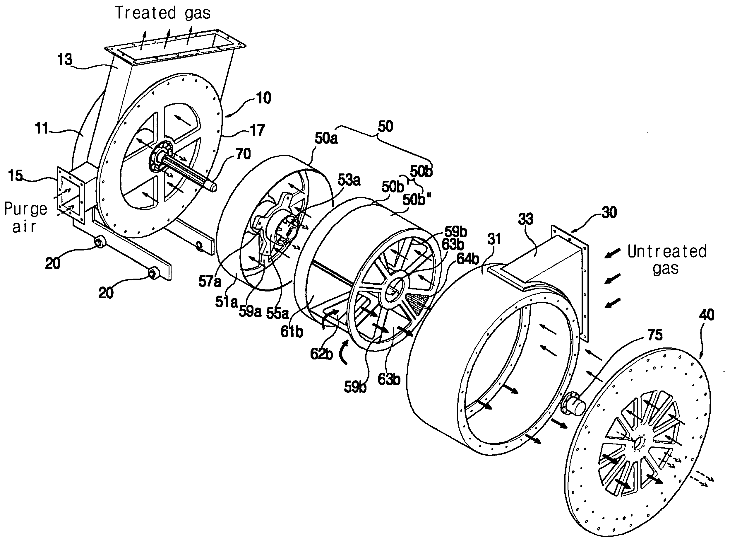
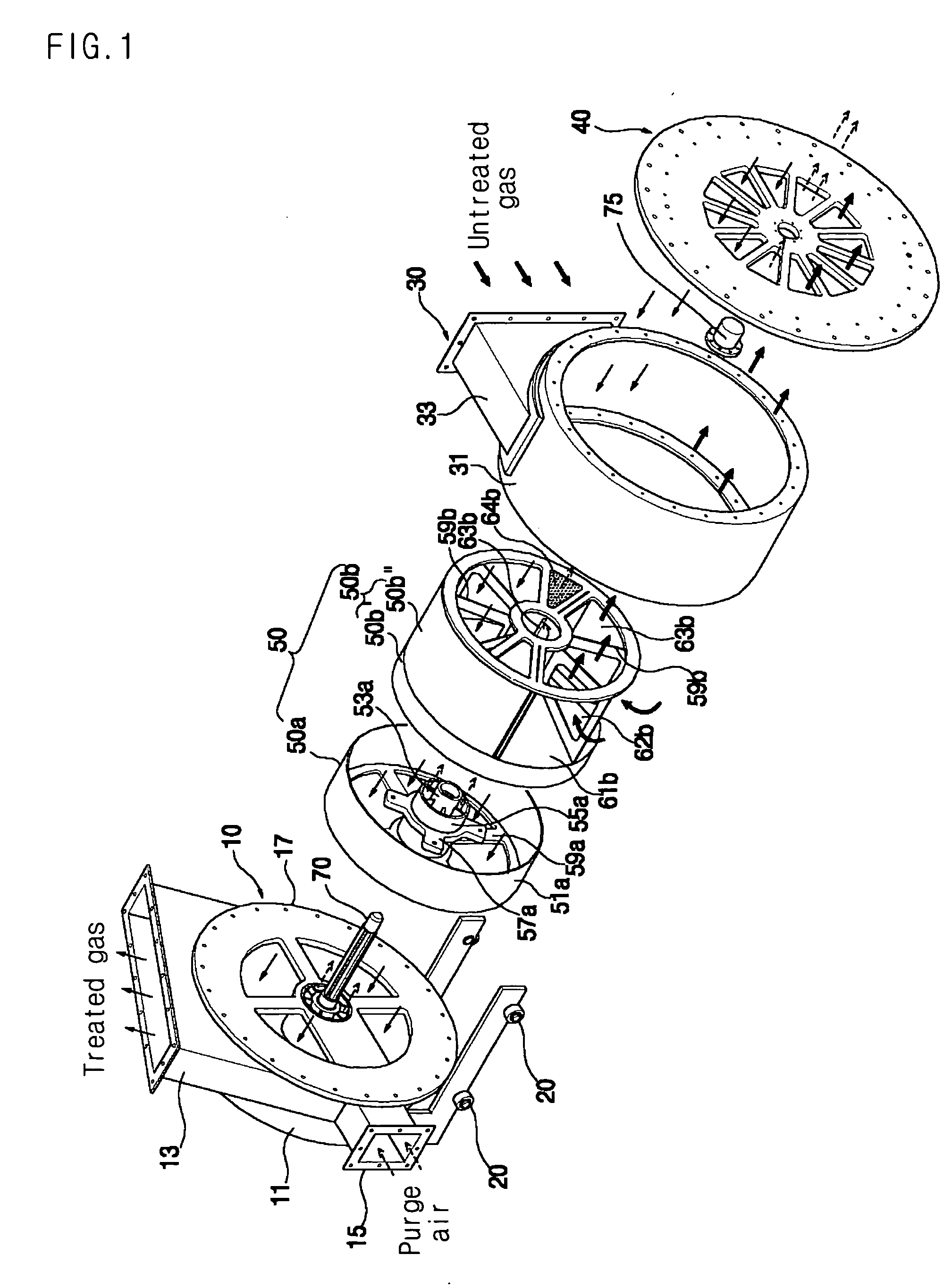
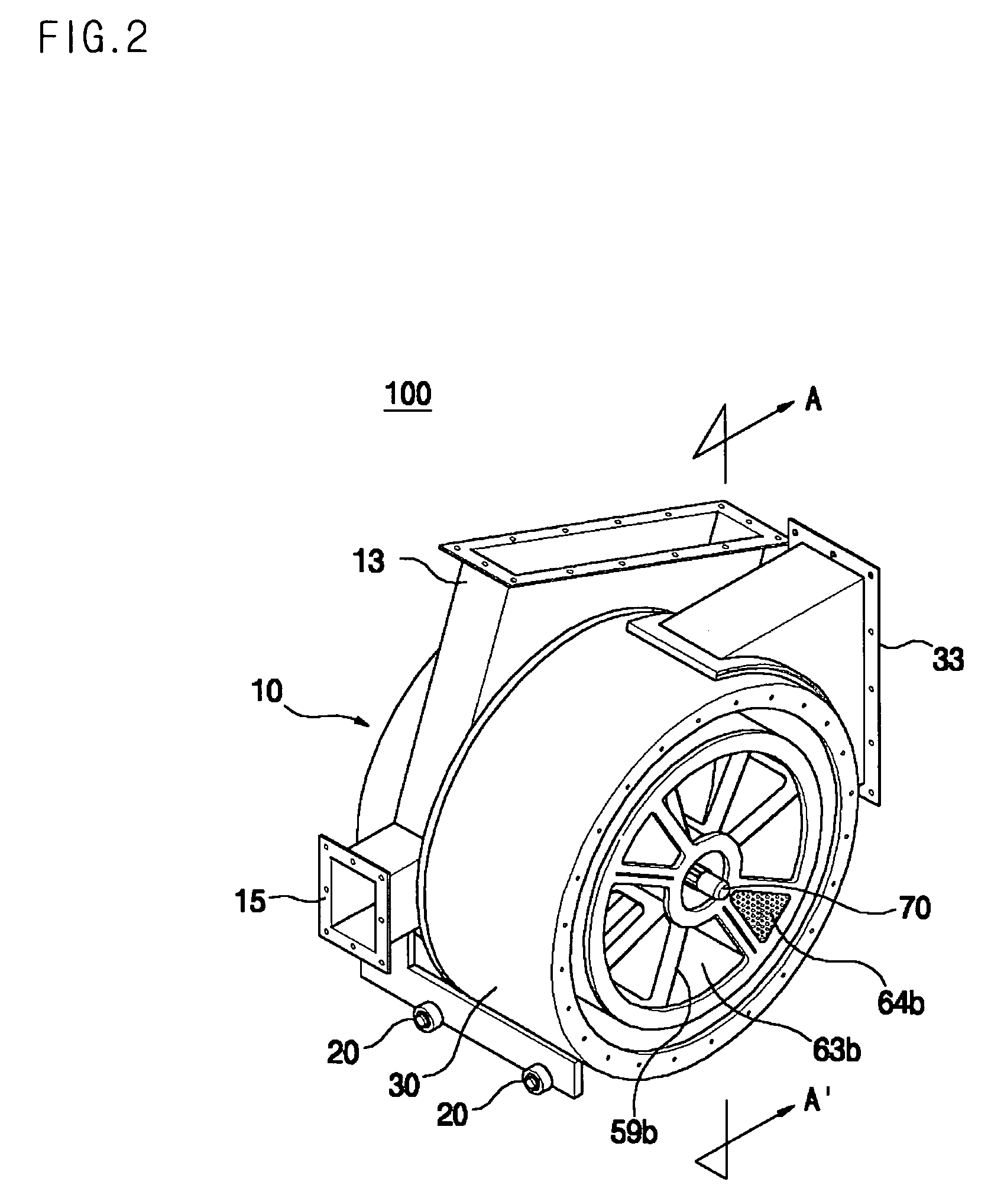
[0026]FIG. 1 is an exploded perspective view of a horizontal rotor distributor in accordance with a preferred embodiment of the present invention. FIG. 2 is an assembled perspective view of the horizontal rotor distributor of FIG. 1, FIG. 3 is a cross-sectional view of the horizontal rotor distributor taken along the line A-A′, and FIG. 4 is a cross-sectional view of the horizontal r...


PUM


Abstract

A separable distribution rotor and a horizontal rotor distributor having the same. The separable distribution rotor includes a first distribution rotor, a second distribution rotor, and an elastic member interposed between the first distribution rotor and the second distribution rotor.

Description

BACKGROUND OF THE INVENTION [0001] 1. Field of the Invention [0002] The present invention relates to a separable distribution rotor and a horizontal rotor distributor having the same, and more particularly to a separable distribution rotor, which is divided into two distribution rotors, and a horizontal rotor distributor having the same. [0003] 2. Description of the Related Art [0004] Conventionally, horizontal rotor distributors are employed by regenerative thermal oxidizers for igniting and purifying volatile organic compounds (VOC). [0005] U.S. Pat. Nos. 5,562,442 and 6,203,316, Japanese Patent Laid-open No. 2001-74225 (dated Mar. 23, 2001), Korean Utility Model Reg. No. 280797 filed by the present applicant, Korean Patent Laid-open No. 2002-25915 (dated Apr. 4, 2002), and Korean Patent application No. 2003-211 disclose regenerative thermal oxidizers. [0006] Since each of the regenerative thermal oxidizers which are disclosed by the above U.S. patent documents and Japanese Patent...

Claims


Application Information

Patent Timeline
Patent Type & Authority Applications(United States)
IPC IPC(8): B01J4/00F16K11/072F03D1/04F23G7/06F27D17/00
CPCF27D17/008B01J4/001F23G7/06
Inventor KWON, SOON-MOKHAN, SEONG-HO
Owner SOON MOK KWON
Why Eureka
Try Eureka