Supply and exhaust pipe

a technology for exhaust pipes and supply pipes, applied in the direction of hose connections, cable terminations, heating types, etc., can solve the problems of reducing sealing efficiency, leaking exhaust gas, and inability to satisfy, so as to improve sealing efficiency, improve sealing efficiency, and increase bending strength

Active Publication Date: 2008-03-25
TOKYO GAS RENOVATION CO LTD
View PDF11 Cites 12 Cited by
  • Summary
  • Abstract
  • Description
  • Claims
  • Application Information

AI Technical Summary

Benefits of technology

[0031]According to one aspect of the invention, by turning up the taper section at the edge of the insert portion to make a double structure, buckling strength at the edge is doubled. As a result, a buckling is unlikely to occur and bending strength is increased, so that the requirement in Japan and the U.S.A. can be satisfied, even in a case of pipes with a large diameter.
[0032]According another aspect of the invention, the modified O-ring contacts closely to the internal surface of the bead for the O-ring along nearly a half of the whole circumference, while to the insert portion, with the modified O-ring being inclined by force generated from the insertion of the insert portion, the modified O-ring contacts closely to the external surface of the insert portion at two points, namely the rim of the cap and the neck. This is to improve sealing efficiency, so that the requirement in terms of sealing efficiency in Japan and the U.S.A. can be satisfied.
[0033]Furthermore, by virtue of forming a solid lubricant layer on the surface of the modified O-ring, sliding becomes smooth. The work of connecting or withdrawing pipes becomes easy, hands do not get dirty, so that workability can be improved.
[0034]According to another aspect of the invention, since substantially all part of the sliding piece is enveloped with the cover, external force is not often applied to the sliding piece. Thus, sliding pieces and locks do not often have trouble, and forming the opening widely along the circumference and forming the engagement of the sliding piece also widely corresponding to this, lead to increased locking strength and stabilization of the lock, so that the requirement in terms of pulling strength in Japan and the U.S.A. can be satisfied.
[0035]According to another aspect of the invention, since the turn-up section reenforces the edge of the opening and works as fulcrum for a seesaw movement of the slide piece, workability is improved.
[0036]According to another aspect of the invention, since the sliding piece is shaped transversely in a concave arc along the external circumferential surface of the supply which is in contact with rear surface of the sliding piece, the engagement slides to the internal bead along to the arc whereby the strength of the lock is increased and the pipe is locked not only stably but also easily.

Problems solved by technology

When extending a duct by connecting pipes, if external force is applied to the duct, stresses across the duct are concentrated to joints, so that these joints may have a buckling, a large bending, disconnection, or decreased sealing efficiency.
However, when performing an impact test in accordance with the standards in the U.S.A. regarding exhaust duct (pipe), “UL1748 Venting System for Gas Burning Appliances, Categories II, II, and IV”, the results cannot satisfy these.
Consequently a leak of exhaust gas may occur.
However, this lubricant is not only messy (it gets one's hands dirty), but also greasy and slippery, so that there is a need for frequent wiping out grease from hands and cleaning, etc. resulting in decreased work efficiency.
To facilitate insertion of a pipe, another method may be considered to set the clearance not so narrow, however, this results in decreased sealing efficiency, particularly when a bending force is applied.
However, some drop-off prevention mechanisms have a structure that once it is locked, it cannot be unlocked later, which is inconvenient, accordingly, there are some provisions of drop-off prevention mechanisms having a configuration such that a locking system can be unlocked by one push.
However, in this known example, since the stopper ring has to be attached to the pipe, this lead to a high cost, and since the structure let the pawl of the stopper ring slide in-and-out to the outer bead, engagement force between the pawl and the outer bead is small, so that its pulling strength is small.
As such, most of the lock member is exposed to the outside of the pipe, and may be deformed by external forces In this way, if the lock member is deformed, operation by use of one's finger tip may become difficult and the lock cannot be disengaged.
This is inconvenient.
H10-26342), as a common disadvantage, these can be used for pipes with a pipe diameter up to about 120 mm, however, in pipes with a larger bore, the engagement width of a pawl is relatively small to the circumference, so that pulling strength becomes smaller, leading to the pipe dropping off easily.

Method used


Image

  • Supply and exhaust pipe
  • Supply and exhaust pipe
  • Supply and exhaust pipe

Examples


example 1

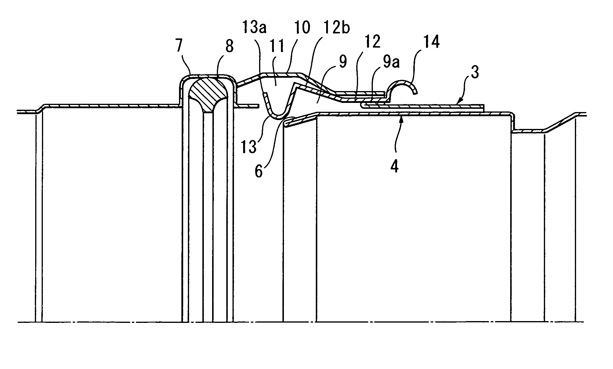
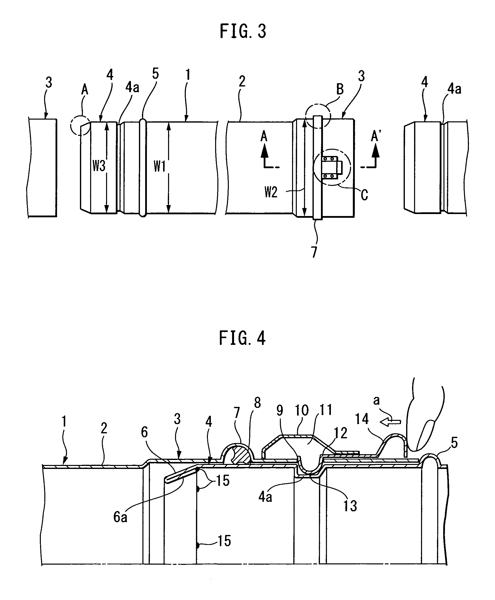
[0066]Example 1 shows an overall view of the present invention, and gives an explanation of the schematic configuration according to FIGS. 3 and 4. Reference numeral 1 designates a supply and exhaust pipe serving a straight pipe section of the supply and exhaust pipes, at one end of which a receptacle 3 is formed, having a slightly larger diameter W2 than a diameter W1 of a body 2.

[0067]Reference numeral 4 designates an insert portion formed on the opposite side to the receptacle 3 in the straight pipe 1, the insert portion 4 having a diameter W3 equal to the diameter W1 of the body 2, which can be inserted into the receptacle 3.

[0068]Reference numeral 4a designates a lock bead (circumferential trough) formed on the circumferential surface of the insert portion 4, the lock bead 4a being engaged by an engagement (as described below) of a sliding piece (as described below) in order to prevent drop-off.

[0069]Reference numeral 5 designates an outer bead (circumferential tube swelling) f...

example 2

[0074]Example 2 relates to the invention with a hemmed section A formed at the edge of an insert portion 4 of a straight pipe 1. This hemmed section A has a double structure as the edge of a taper section 6 is inwardly turned up to form a turn-up 6a. It is desirable, in terms of strength, to take the width of this turn-up 6a as large as possible.

[0075]Furthermore, the turn-up 6a may be left as turned-up, but also it can increase strength by 5 to 10% by performing spot welding 15 of the edge of the turn-up 6a onto the internal surface of the pipe. Welding may performed around the entire circumference instead of a spot, however, this operation will be time-consuming and result in a high cost, accordingly, spot welding will be sufficient if welding is required.

[0076]Three or four points at regular intervals may be enough as points to be spot-welded 15, but also more points may be welded.

[0077]The turn-up 6a is to lie inside in the hemmed section A in principle, but it may also lie outs...

example 3

[0080]Example 3 corresponds to the invention with a sealing system when inserting an insert portion 4 into a receptacle 3. The configuration and functions will be explained in detail with reference to FIGS. 7 to 11.

[0081]FIGS. 7 to 9 shows a modified O-ring 8. This modified O-ring 8 is made from rubber, of which the hardness is equivalent to that of O-rings generally used for supply and exhaust pipes. However, the shape of its cross-section, not a circle, comprises a cap 8a, and a neck 8b facing to the center of the pipe from the central of the cap 8a, presenting a mushroom shape.

[0082]This modified O-ring 8 is integrated within the O-ring bead 7 as shown in FIGS. 4, 10 and 11, the edge of the neck 8b (the internal diameter) is slightly projected from the external diameter of the insert portion 4 towards the center of the pipe.

[0083]Consequently, when the insert portion 4 is inserted into the receptacle 3 as shown in FIG. 10, the edge of the neck 8b of the modified O-ring 8 is pushe...


PUM


Abstract

In order to provide a supply and exhaust pipe comprising a drop-off prevention mechanism, particularly effective for pipes with a large diameter, to increase bending strength and sealing efficiency, formation of a hemmed section A at an top edge of an insert portion 4 can eliminate the occurrence of buckling and increase bending strength. Furthermore, an O-ring for sealing can improve sealing efficiency and also can make itself follow a deformation of the pipe by forming it into a mushroom shape to establish close contacts to the pipe at two points, namely a neck 8b and a part of the circumference 8c of a cap 8a. Furthermore, a drop-off prevention mechanism of the pipe has a wide sliding piece 12, and an arc 17 with a curvature adapted to the curvature of the pipe is formed on the lower surface of the sliding piece 12, to stabilize its sliding.

Description

CROSS REFERENCE TO RELATED APPLICATIONS[0001]This application claims the benefit of priority under 35 U.S.C. § 119 of Japan Application 2004-341791 filed Nov. 26, 2004, the entire contents of which are incorporated herein by reference.BACKGROUND OF THE INVENTION[0002]1. Field of the Invention[0003]The present invention relates to a supply and exhaust pipe for an appliance with burning, or a supply and exhaust pipe for ventilation by taking fresh air into a room and / or emitting air from the room to the outside, the supply and exhaust pipe being used for constructing a duct by adding and connecting regular size pipes at site. More specifically, the present invention relates to a supply and exhaust pipe as mentioned having increased bending strength and sealing efficiency at joints when connecting supply and exhaust pipes, and a drop-off prevention function, particularly effective for pipes with a large diameter.[0004]2. Description of the Related Art[0005]For an appliance with a burne...

Claims


Application Information

Patent Timeline
Patent Type & Authority Patents(United States)
IPC IPC(8): F16L35/00
CPCF16L21/03F16L21/08F16L37/0985F16L37/133F24F13/0209F23J13/04F23J2213/202F23J2213/204
Inventor NOHARA, MASAHIKOHIRUMA, NORIO
Owner TOKYO GAS RENOVATION CO LTD
Why Eureka
Try Eureka