Caliper for disc brake

Active Publication Date: 2016-01-07
FRENI BREMBO SPA
View PDF13 Cites 18 Cited by
  • Summary
  • Abstract
  • Description
  • Claims
  • Application Information

AI Technical Summary

Benefits of technology

[0010]Therefore, the object of the present invention is to eliminate, or at least reduce, the prior art problems mentioned above with a caliper for disc brake which allows to significantly reduce the presence of residual braking torques.
[0011]According to a preferred embodiment, such problems are solved by a caliper for disc brake comprising a first thrust spring which exerts a thrust on the pad, said thrust having a first axial component towards the pistons and a first radial component perpendicular to said axial direction and substantially incident to the ro

Problems solved by technology

In the braking release step, the piston stops exerting the thrust action; however, the pad that is in contact with the braking band tends to remain in position, generating a residual braking torque and an annoying noise and a perceived vibration at the wheel.
However, prior art solutions have several drawbacks.
Such a torque tends to rotate the pad with negative effects both in terms of retraction and in terms of wear of the pad itself.
In

Method used


Image

  • Caliper for disc brake
  • Caliper for disc brake
  • Caliper for disc brake

Examples


Example

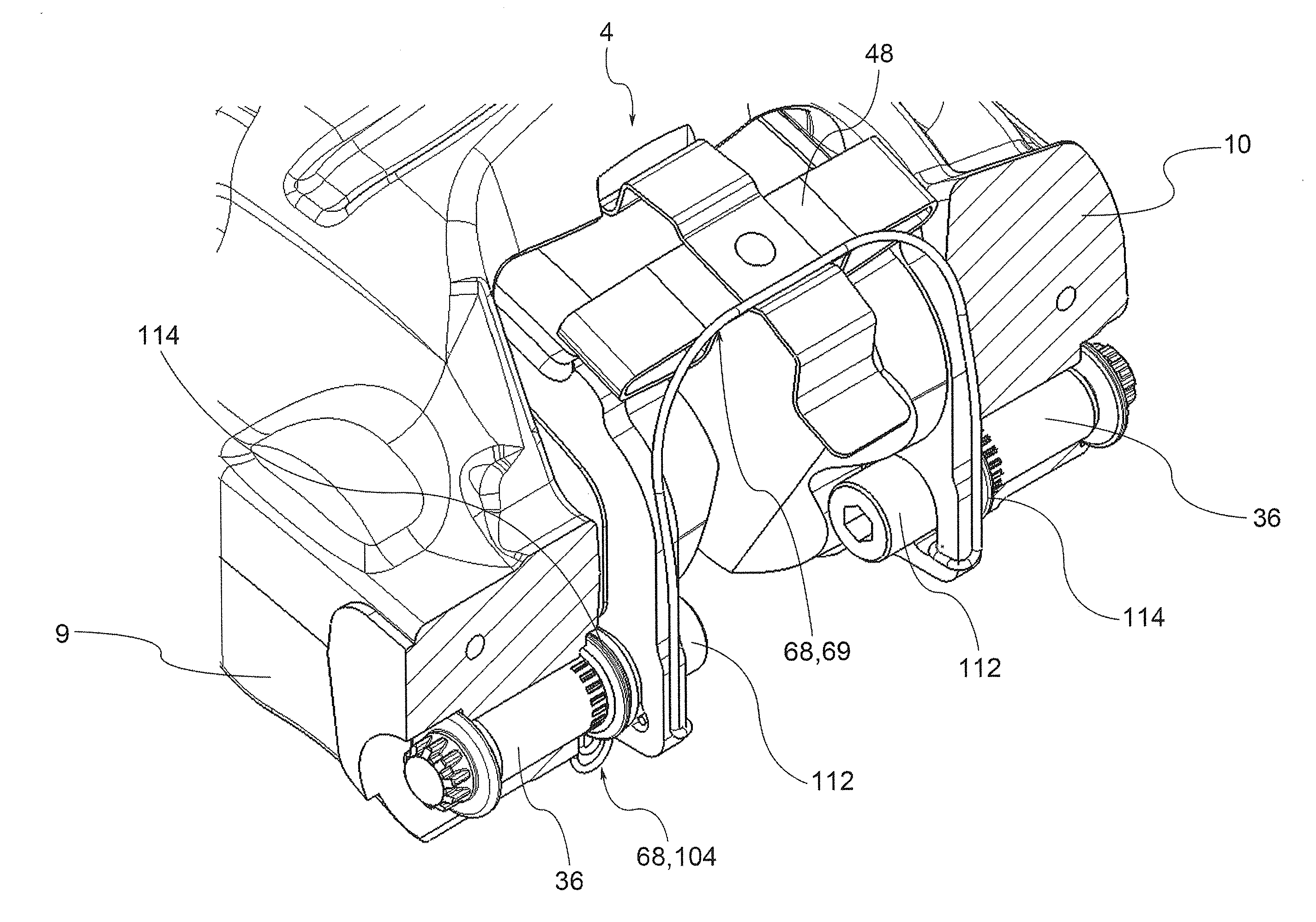
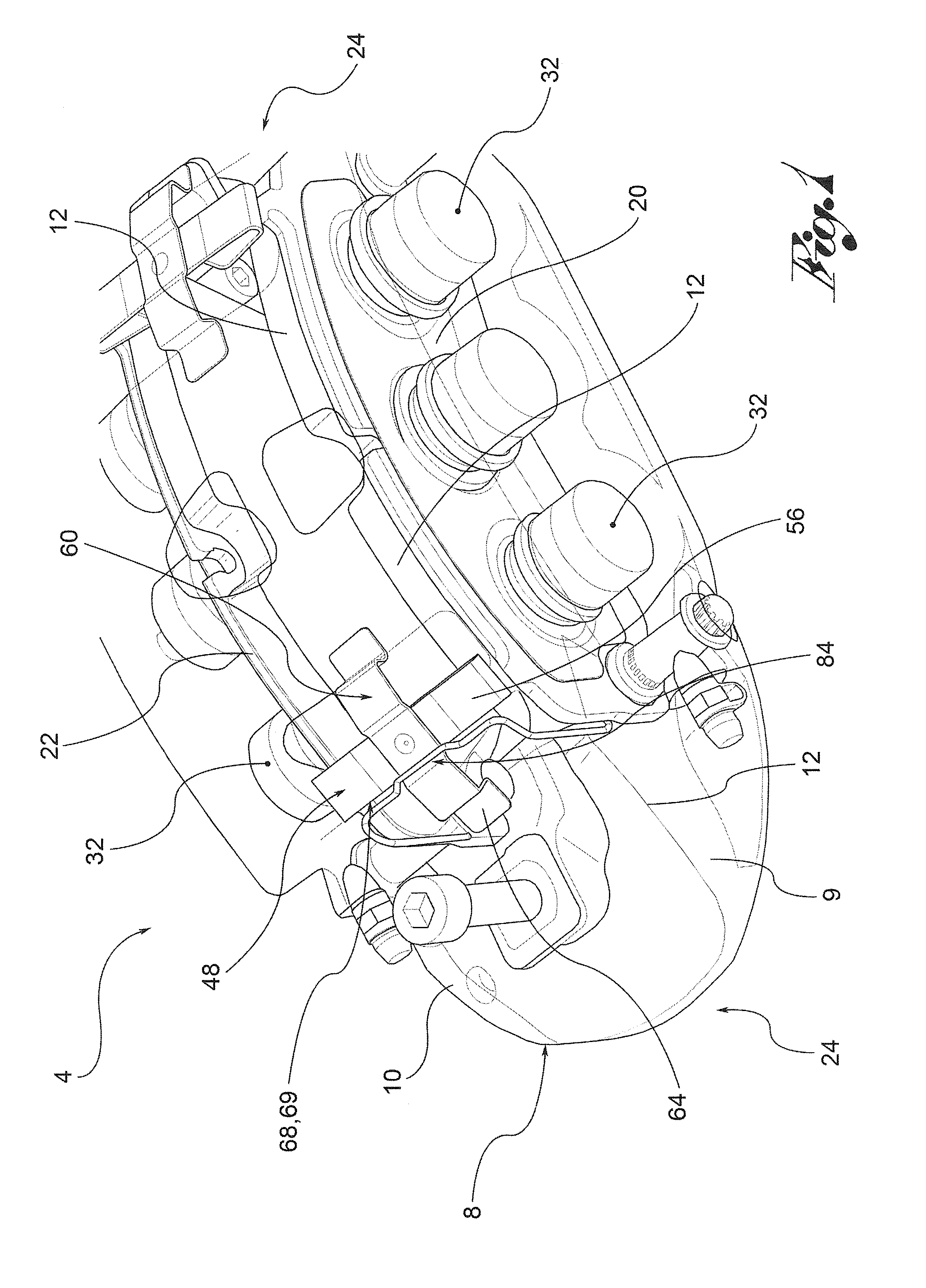
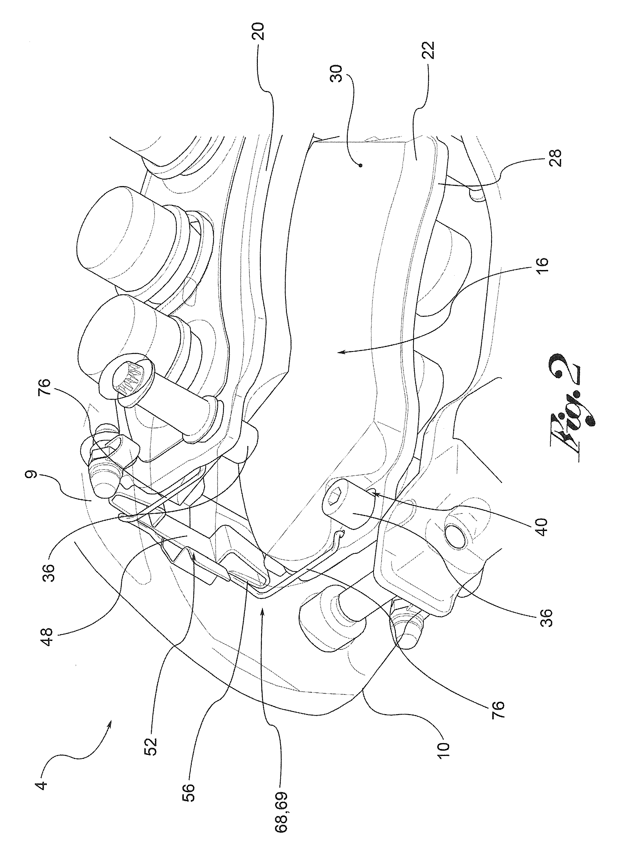
[0034]With reference to the drawings, reference numeral 4 indicates as a whole a caliper for disc brake having a caliper body 8 provided with a pair of half-bodies 9, 10 connected to each other by means of at least one connection bridge 12.

[0035]The caliper body 8 may be of the monobloc type, in which the half-bodies 9, 10 are integral to each other, or the half-bodies 9, 10 may be mechanically joined together for example by means of threaded connection means.

[0036]The caliper body 8 may be fixed or floating.

[0037]The caliper body 8 defines at least partially a housing compartment 16 for an associable disc brake (not shown) and houses at least one pair of pads 20, 22 positioned on sides opposite said housing compartment 16 in an axial direction X-X.

[0038]The housing compartment 16 has a disc-sector shape and is radially delimited by one or more connection bridges 12.

[0039]By radial direction R-R it is meant a direction perpendicular to the axial direction X-X and directed towards th...


PUM


Abstract

The invention relates to a caliper for disc brake comprising a caliper body which defines a housing compartment for an associated brake disc and houses at least one pair of pads arranged on opposite sides of the housing compartment along an axial direction. The caliper body comprises at least one thrust piston axially operable against the pad, at least one axial guide which supports and guides the pad in the axial direction and a first thrust spring which exerts a thrust on the pad. Said thrust has a first axial component, axially directed in a direction of approach to the pistons, and a first radial component, perpendicular to the axial direction. Advantageously, the caliper body comprises at least one compensation spring which exerts an axial thrust on the pad in a direction of approach to the pistons. The second axial component annuls the momentum given by the friction force exchanged between the pad and the axial guide with respect to the point of application of the first axial component on the pad.

Description

FIELD OF APPLICATION[0001]The object of the present invention is a caliper for disc brake.[0002]The caliper for disc brake according to the present invention is particularly, but not exclusively, applied in the automotive industry.BACKGROUND ART[0003]As known, in calipers for disc brakes, the pads are pressed by at least one piston against the braking band of the associable brake disc. In the braking release step, the piston stops exerting the thrust action; however, the pad that is in contact with the braking band tends to remain in position, generating a residual braking torque and an annoying noise and a perceived vibration at the wheel.[0004]For this reason, it is known to provide the calipers with plates or springs which exert a thrust action on the pads away from the brake disc. Obviously, during the braking step, such a thrust action is overcome by the braking action exerted by the pistons, but in the release step, said plates exert a thrust sufficient to move the pads away f...

Claims


Application Information

Patent Timeline
IPC IPC(8): F16D65/097F16D55/2265
CPCF16D65/0977F16D65/0975F16D55/2265F16D65/0974
Inventor CRIPPA, CRISTIANFATTORI, GIOVANNITERUZZI, ANDREA
Owner FRENI BREMBO SPA
Why Eureka
Try Eureka