Integrated fluidic connection of planar structures for sample separation devices

Active Publication Date: 2016-01-07
AGILENT TECH INC
View PDF3 Cites 2 Cited by
  • Summary
  • Abstract
  • Description
  • Claims
  • Application Information

AI Technical Summary

Benefits of technology

[0040]In an embodiment, the connection between the planar structure and the female adapter piece is formed at a locally narrowed end of the planar structure which locally narrowed end has a width which is smaller than (for instance is at least one half or is at least one tenth of) a width of a remaining portion of the planar structure and extends at least partially into the female adapter piece. Hence, an appendix or a tip or a neck or a taper may be inserted into the reception of the female adapter piece, whereas a wider, integrally connected portion of the flat or planar structure may remain outside of the reception. Thus, the mechanical robustness of the connection may be improved and the fluidic connection between the fluid channel and the fluid conduit may be achieved with reduced gap or even without any gap in between.
[0041]In an embodiment, the con

Problems solved by technology

However, the requirements regarding sealing performance and mechanical stability of a fluidic component of fluidic measurement devices increases with furth

Method used


Image

  • Integrated fluidic connection of planar structures for sample separation devices
  • Integrated fluidic connection of planar structures for sample separation devices
  • Integrated fluidic connection of planar structures for sample separation devices

Examples


Example

[0064]The illustration in the drawing is schematically.

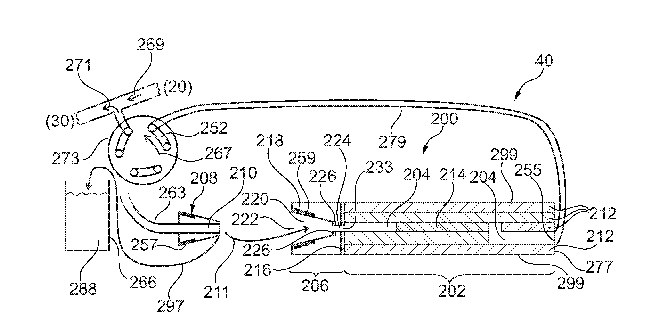
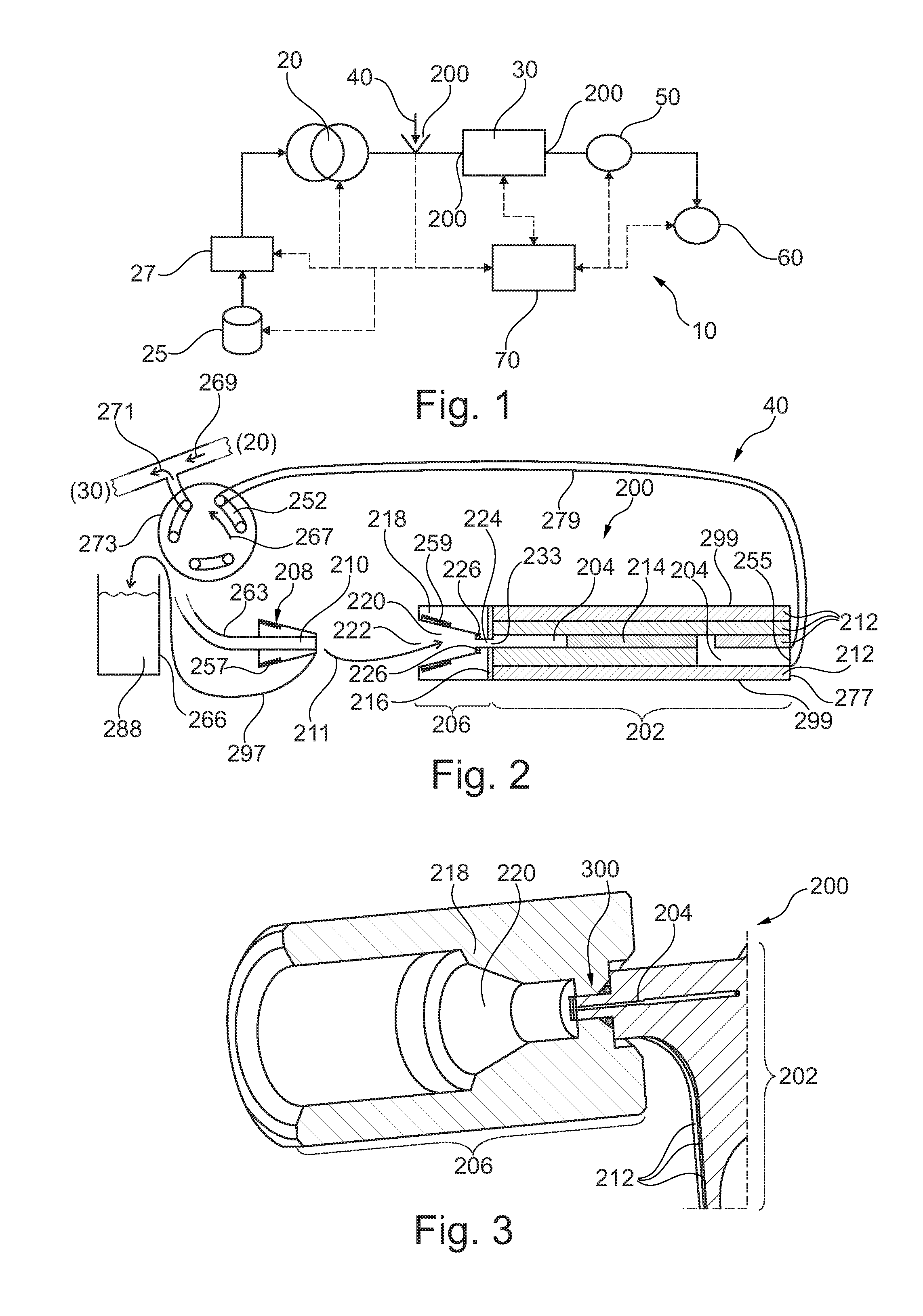
[0065]Referring now in greater detail to the drawings, FIG. 1 depicts a general schematic of a liquid separation system 10. A pump 20 receives a mobile phase from a solvent supply 25, typically via a degasser 27, which degases and thus reduces the amount of dissolved gases in the mobile phase. The pump 20—as a mobile phase drive—drives the mobile phase through a separating device 30 (such as a chromatographic column) comprising a stationary phase. A sampling unit or injector 40 can be provided between the pump 20 and the separating device 30 in order to subject or add (often referred to as sample introduction) a sample fluid into the mobile phase. The stationary phase of the separating device 30 is configured for separating compounds of the sample liquid. A detector 50 is provided for detecting separated compounds of the sample fluid. A fractionating unit 60 can be provided for outputting separated compounds of sample fluid.

[006...


PUM

PropertyMeasurementUnit
Flow rateaaaaaaaaaa
Structureaaaaaaaaaa
Widthaaaaaaaaaa

Abstract

A fluidic device (200), comprising a planar structure (202) constituted by a plurality of laminated layers (212) and accommodating a fluid channel (204) extending up to a surface of the planar structure (202), and a female adapter piece (206) configured for a fluid-tight accommodation of a male adapter piece (208) having a fluid conduit (210), wherein the female adapter piece (206) is connected or connectable with the planar structure (202) so that, when the male adapter piece (208) is accommodated in the female adapter piece (206), the fluid conduit (210) is brought in fluid-tight fluid communication with the fluid channel (204), wherein the fluid channel (204) is exposed to the female adapter piece (206) at a lateral surface of the planar structure (202) at which the laminated layers (212) are exposed.

Description

BACKGROUND ART[0001]The present invention relates to fluidically coupling fluidic components, in particular in a high performance liquid chromatography application.[0002]In liquid chromatography, a fluidic sample (mobile phase) may be pumped through conduits and a column comprising a material (stationary phase) which is capable of separating different components of the fluidic analyte. Such a material, so-called beads which may comprise silica gel, may be filled into a column tube which may be connected to other elements (like a sampling unit, a flow cell, containers including sample and / or buffers) by conduits.[0003]The flow path of the mobile phase typically comprises plural individual components coupled together, which, in turn, might also be comprised of individual sub-components. Due to the high pressure applied in most HPLC applications, pressure sealing of the components in and along the flow path is required. Sealings should also provide for a small dead volume and low carry...

Claims


Application Information

Patent Timeline
IPC IPC(8): F16L21/02B01D15/10B01D15/14C12M1/12C12M3/00F16L13/02F16L13/08F16L13/10F16L15/04F16L47/02F16L47/16G01N30/16G01N30/60
CPCF16L21/02F16L13/0209F16L13/08F16L13/103F16L15/04F16L47/02G01N2030/027B01D15/14B01D15/10G01N30/16G01N30/60C12M23/04C12M23/46F16L47/16B01L3/502715G01N30/6026G01N30/6095B01L3/565B01L2200/027B01L2200/0689
Inventor ZEKO, DARIJOBERNDT, MANFRED
Owner AGILENT TECH INC
Why Eureka
Try Eureka