Electrical heating element and a method for its production

Inactive Publication Date: 2011-07-14
HE SYST ELECTRONICS
View PDF3 Cites 0 Cited by
  • Summary
  • Abstract
  • Description
  • Claims
  • Application Information

AI Technical Summary

Benefits of technology

[0030]The attachment of the second ceramic substrate results in a layer structure which allows improved mechanical robustness and a high electrical withstand voltage. Electrical voltages of more than 500 V are possible. Complete coverage of th

Problems solved by technology

However, the flat heating element has a low withstand voltage and a short life as well.
This method is therefore complex and expensive.
Furthermore, shrinkage occurs

Method used


Image

  • Electrical heating element and a method for its production
  • Electrical heating element and a method for its production

Examples


Example

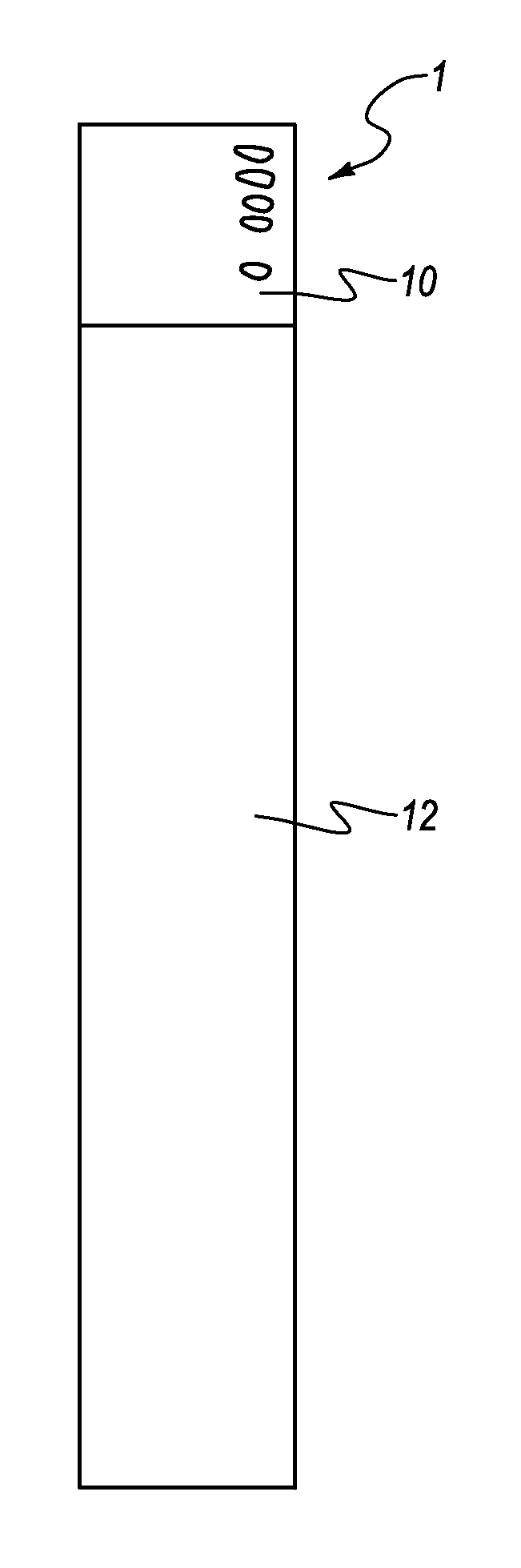
[0039]FIG. 1 shows a plan view of a heating element according to one preferred embodiment of the invention.

[0040]The heating element 1 has a first area 10 with electrical connections, and preferably with an electronic circuit for open-loop and / or closed-loop control of the heating element. The heating element 1 furthermore has a second area 12 with the actual heating element.

[0041]In this specific embodiment, the heating element 1 together with the first and second areas 10 and 12 has a total length of 152 mm, and a width of 24.5 mm. The second area 12, that is to say the actual heating element, in this example has a length of 126.5 mm and a width of 24.5 mm.

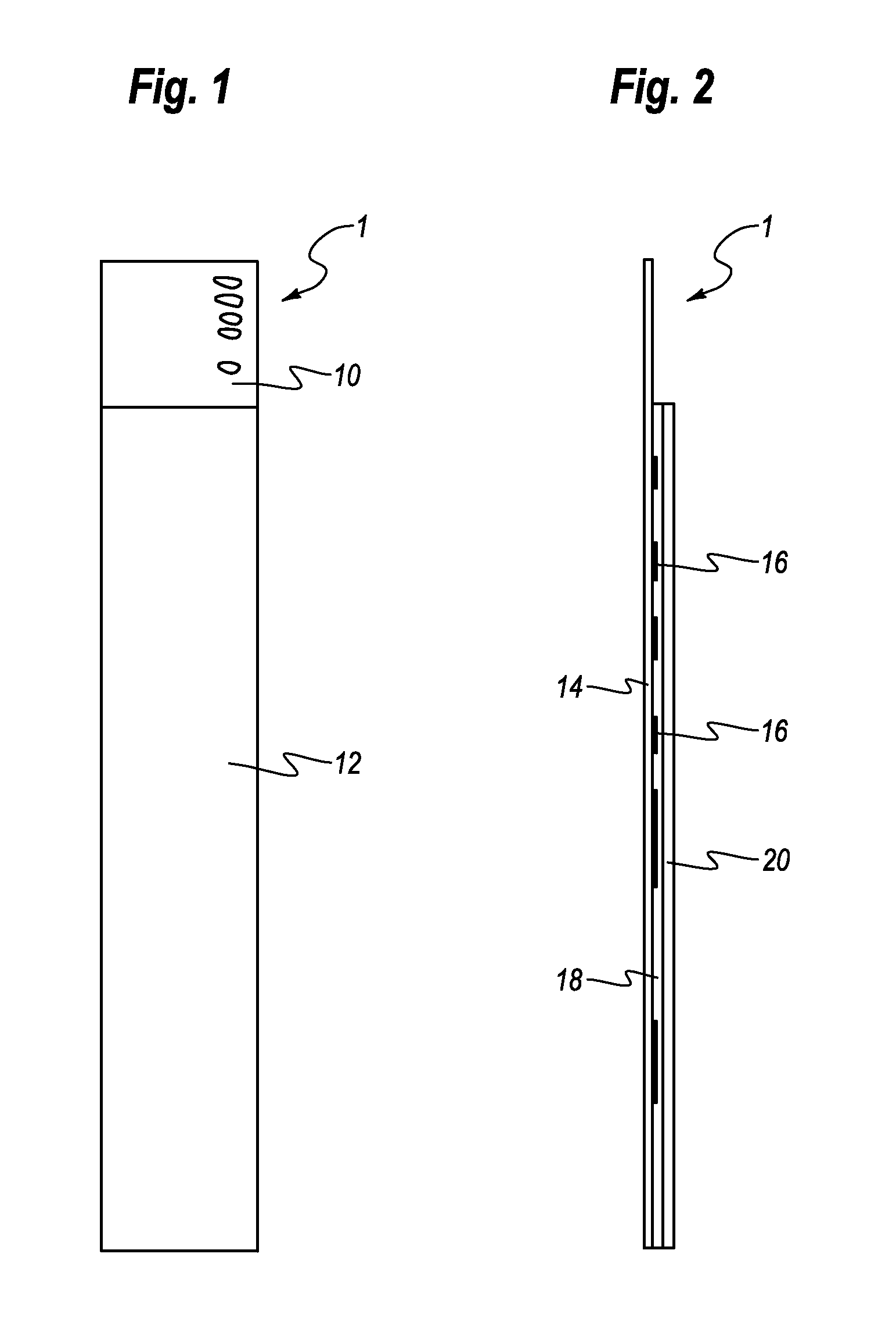
[0042]FIG. 2 shows a side section view of the heating element 1 according to the preferred embodiment of the invention. FIG. 2 shows the layer structure of the heating element according to the invention. FIG. 2 illustrates the layer thickness of the heating element as being considerably thicker than in an illustration which is t...


PUM

PropertyMeasurementUnit
Melting pointaaaaaaaaaa
Electrical resistanceaaaaaaaaaa

Abstract

The invention relates to an electrical heating element which is in the form of a flat piece and has the following layers: a first ceramic substrate in a burnt state, a resistance layer composed of a resistance material which is applied to the first ceramic substrate, a low-melting-point glass layer, which completely covers the resistance layer 16, such that the resistance layer is an integral component of the glass layer, and a second ceramic substrate in a burnt state, which completely covers the glass layer. The invention also relates to a method for its production.

Description

CROSS-REFERENCE TO RELATED APPLICATIONS[0001]The present invention claims the benefit of priority to German Patent Application NO. DE 10 2010 000 042.6, filed Jan. 11, 2010, entitled “Elektrisches Heizungselement und ein Verfahren zu dessen Herstellung,” the entire content of which is incorporated by reference herein.BACKGROUND OF THE INVENTION[0002]1. The Field of the Invention[0003]The invention relates to an electrical heating element which is in the form of a flat piece. The invention also relates to a method for its production.[0004]2. Background and Relevant Art[0005]By way of example, electrical heating elements may be in the form of heaters, supplementary heaters or additional heaters, and it should be possible to produce them at least comparatively easily, to operate them as reliably as possible, and for them to be as resistant to wear as possible.[0006]Electrical heating elements such as heaters, supplementary heaters or additional heaters may, according to the prior art, ...

Claims


Application Information

Patent Timeline
IPC IPC(8): H05B3/10H01C17/02
CPCH05B3/265Y10T29/49083H05B2203/017H05B2203/013
Inventor ASSMAN, KLAUSSBARNERT, ARMIN
Owner HE SYST ELECTRONICS
Why Eureka
Try Eureka