Motor

Pending Publication Date: 2019-04-04
ROMAX TECH
View PDF0 Cites 9 Cited by
  • Summary
  • Abstract
  • Description
  • Claims
  • Application Information

AI Technical Summary

Benefits of technology

[0009]In order to solve the above problems and achieve the object, an aspect of the present invention is two dimensionally flux focused rotor assembly having mechanical connection between electromagnetically active components and shaft allowing for transfer of torque to or from system in which it is integrated. In addition, magnetic flux l

Problems solved by technology

Additionally, power loss of electromagnetic nature, particularly due to flow of eddy currents in solid bodies, could be present in electrically conductive parts of the rotor.
Ensuring isotropic properties and limiting power loss at the same time is challenging.
This can happen during normal operation or under fault conditions and is of particular concern when cheap magnets with low coercive force are used.
Rotor design employing low coercive force magnets able to resist demagnetisation is difficult to achieve.
Leakage flux in an electrical machine is a portion of flux which does not contribute to electromechanical energy conversion, is normally considered parasitic.
Structural components of the rotor, having relative permeability hi

Method used


Image

  • Motor
  • Motor
  • Motor

Examples


Example

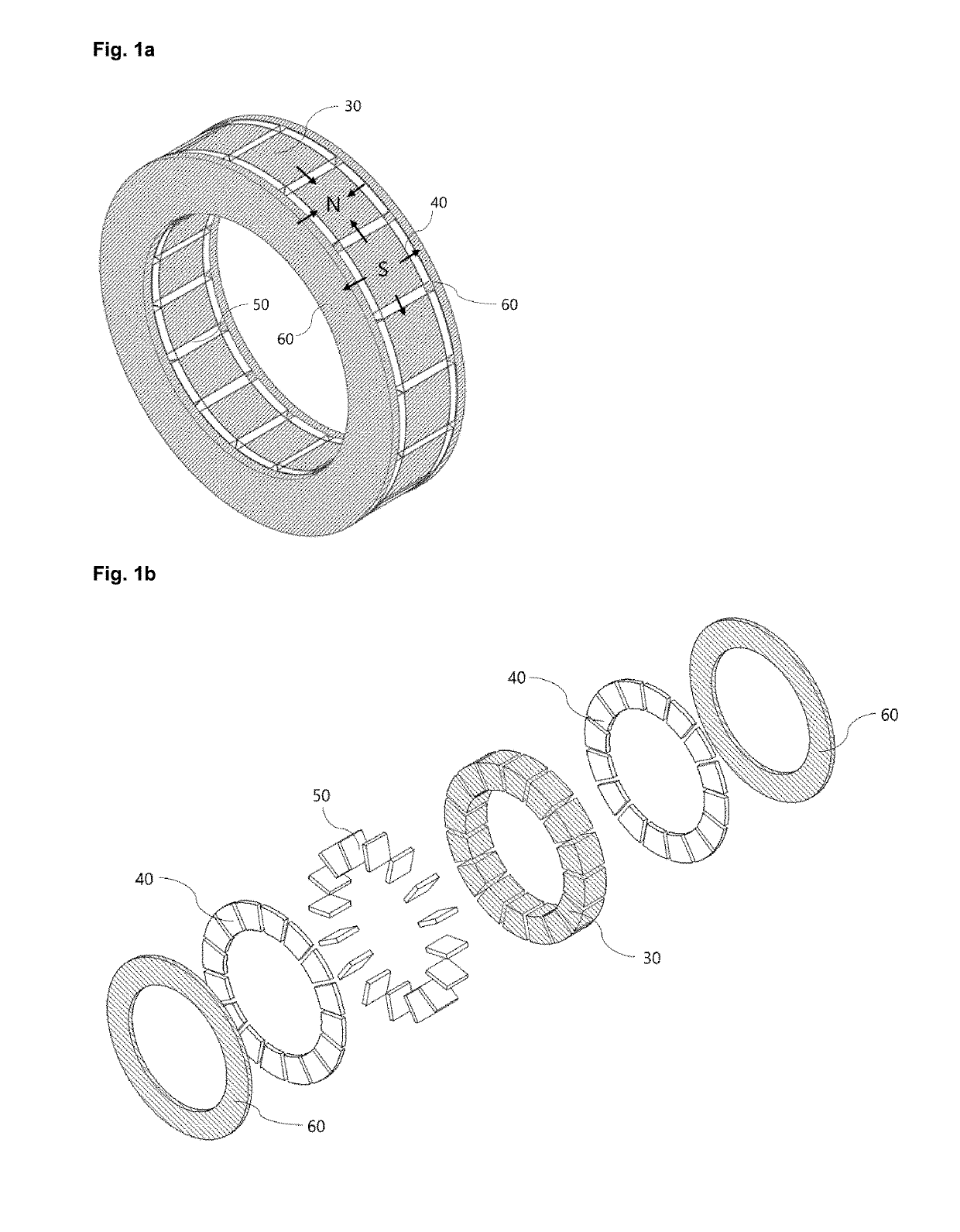
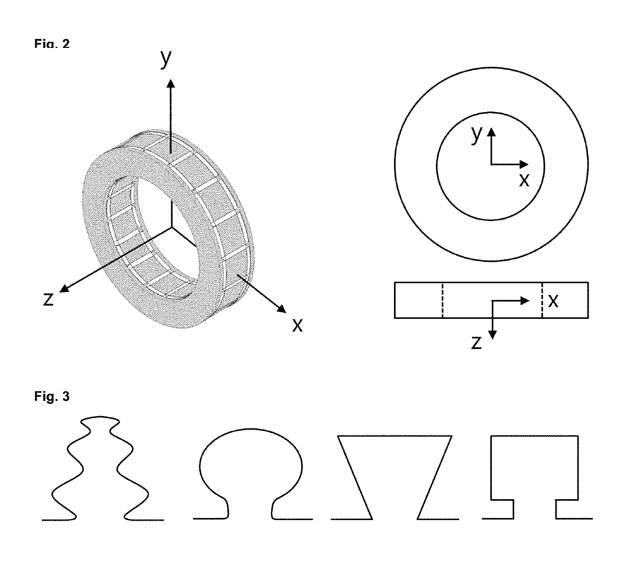
[0055]Referring to FIG. 1a and FIG. 1b, which respectively show an assembled and exploded view of the fundamental components of the permanent magnet rotor and a co-ordinate system used in the following description of the embodiments, a general arrangement of a permanent magnet rotor for an electrical machine employing two dimensional flux focusing is disclosed. The direction of magnetisation for the magnets is shown by arrows in FIG. 1a.

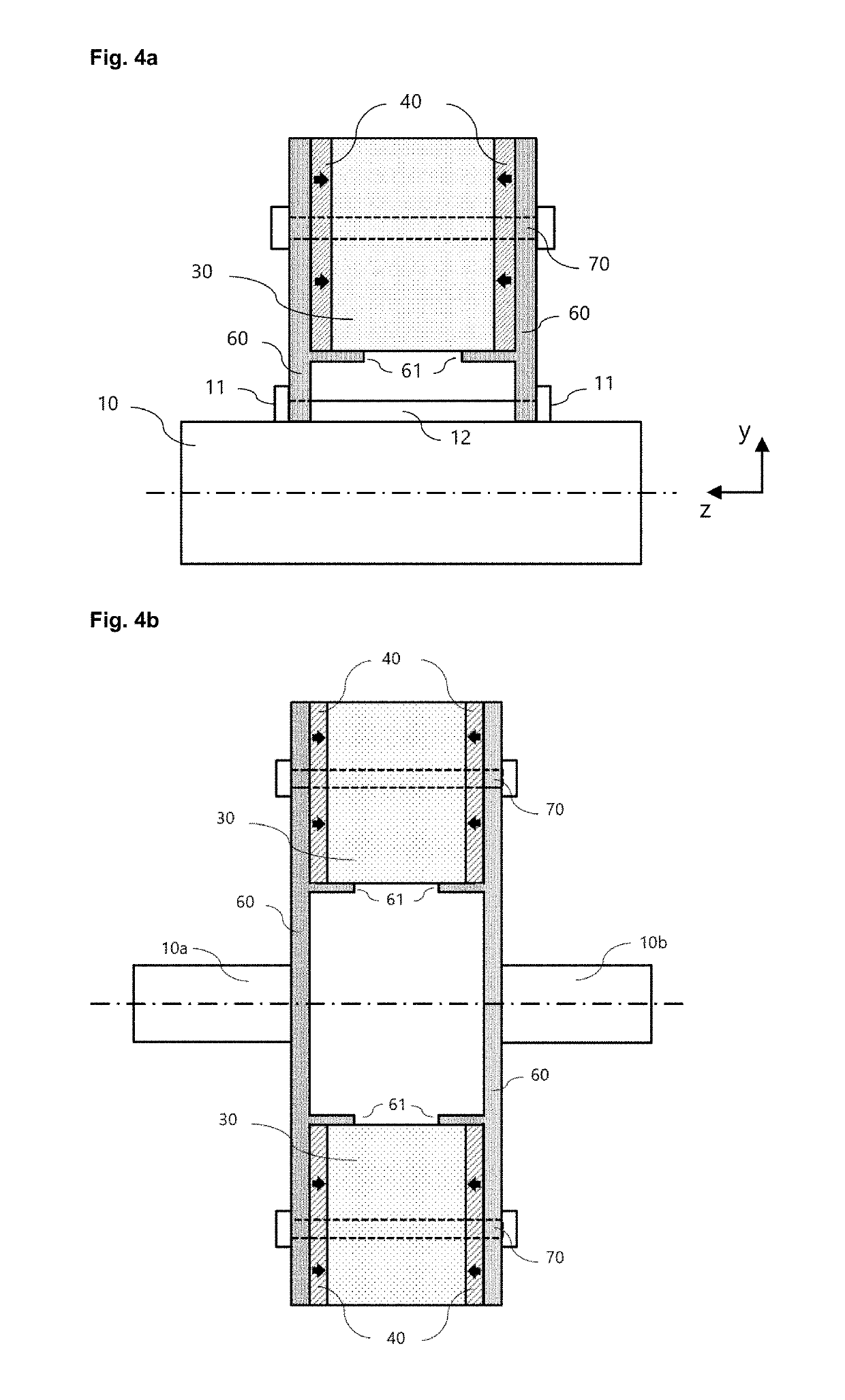
[0056]Fundamental (active) components of the permanent magnet rotor are magnetic pole pieces 30, magnetic end-plates 60, circumferentially magnetised magnets 50 and magnets providing flux in axial direction 40. Within each array of circumferentially magnetised magnets 50 and magnets providing flux in axial direction 40, the circumferentially adjacent magnets are magnetised in opposite directions to each other. Within each array, there is one magnet corresponding to each pole piece. The magnetic end-plates 60 and the magnetic pole pieces30 are magnet...


PUM


Abstract

Construction of a permanent magnet rotor assembly having a plurality of magnetic poles and comprising a number of magnetic pole pieces arranged in circular array. Two sets of permanent magnets—one set magnetised in circumferential direction of the rotor and the second set providing flux in axial direction of rotor, generating a magnetic flux focused through the pole piece and interacting with the magnetic flux of the stator. End-plates made of magnetic material are present such there is an axial gap between the them and the array of magnetic pole pieces. Circumferentially magnetised magnets are placed in the circumferential gaps between the pole pieces, whereas the magnets providing flux in axial direction are placed in the gaps between the array of pole pieces and end-plates.

Description

BACKGROUND OF THE INVENTION[0001]The present invention is related to permanent magnet motors.[0002]A concept of two dimensionally flux focused radial field rotor for an electrical machine was disclosed by K. Atallah and J. Wang (A rotor with axially and circumferentially magnetized permanent magnets, IEEE Transactions on Magnetics, Nov. 2012). The concept utilizes two sets of magnets, one set providing flux in circumferential direction and the other in axial direction. Magnetic flux generated by both sets of magnets is guided towards the electrical machine air gap by magnetic pole pieces. Additionally, magnetic end-plates are utilized to provide return path for the flux travelling in axial direction. Due to the aforementioned two-dimensional flux focusing, air gap flux density could be substantially higher than remanent flux density of permanent magnets employed in the rotor. A similar concept was disclosed by Matsuhashi et al. (Comparison study of various motors for EVs and the pot...

Claims


Application Information

Patent Timeline
IPC IPC(8): H02K15/03
CPCH02K15/03H02K1/2773H02K1/2713H02K1/272Y02T10/64H02K1/278H02K1/28H02K1/30H02K21/14H02K1/2753H02K2201/03
Inventor GOEL, ASHISHJAKUBASZEK, MAREKCHMELICEK, PETR
Owner ROMAX TECH
Why Eureka
Try Eureka