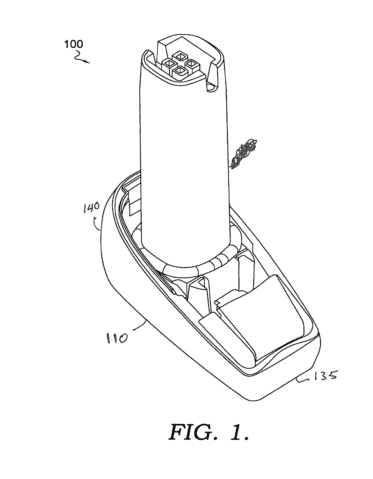
[0024]Embodiments of the invention include a battery pack 100 as shown in FIG. 1 that prevents damage and malfunctions to the Li-ion cell (i.e. battery cell). The battery pack 100 includes a fast release system that is part of an innovative system to lock and unlock (205) the battery pack in and from the device. The aim of the disclosure is to provide a more safe and user-friendly battery pack that can be used and changed very quickly, avoiding any leakage. Moreover, the Li-ion cell is protected with a 6-axis damping solution.
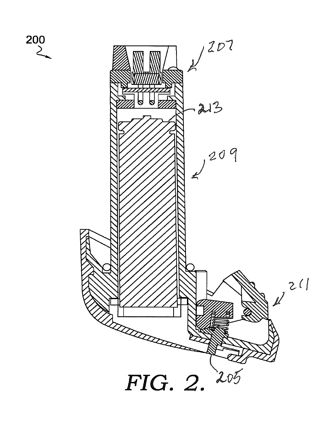
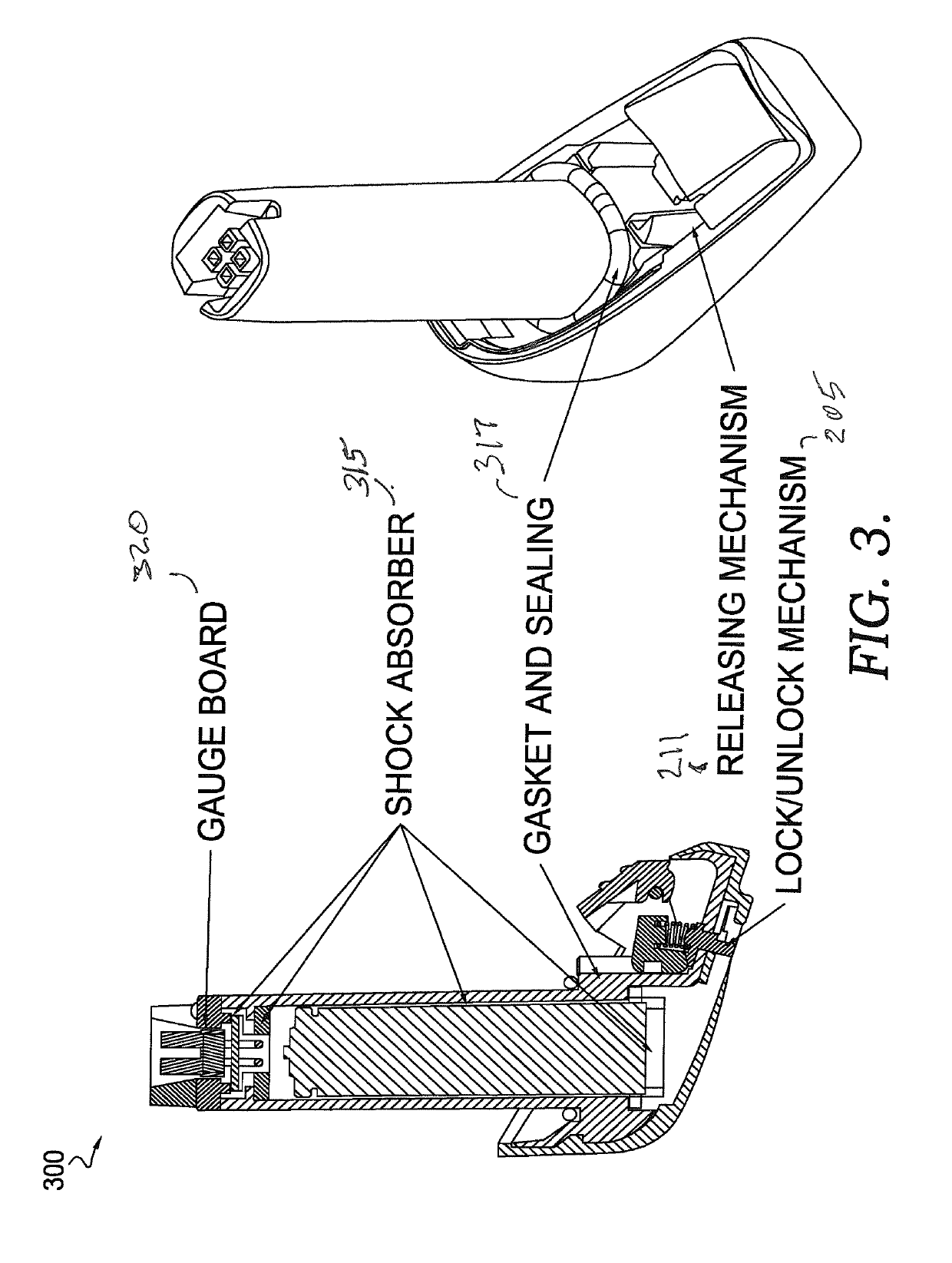
[0025]Turning now to FIG. 2, a cross-sectional view 200 of battery pack 100 is shown having three sections: A connection area 207; a cell box 209 that contains a battery cell 213; and a release mechanism 211 with lock/unlock system 205.
[0026]Embodiments of the invention are related to an innovative battery pack for an industrial handheld scanner, with a double system of locking: Standard locking of the battery pack inside the handle component; and secure locking to prevent accidental extraction of the battery pack due to floor drops or abnormal usage by the operator.
[0027]Embodiments of the invention include a battery pack for industrial optical code readers. For example, optical code readers include camera devices that may in turn comprise an array of optical detectors and a uniform light source, such as a light emitting diode (LED), used to illuminate a surface. The optical detectors may be charge-coupled devices (CCDs), complementary metal-oxide semiconductor (CMOS) devices, or other suitable devices, and they may be implemented in a one-dimensional or two-dimensional array. In operation, when light from the light source reflects from the surface or from the surface of an object, the array detects the reflected light to capture an image. Systems with one-dimensional arrays capture sequential linear cross-sections that collect to form a two-dimensional image, whereas two-dimensional arrays repeatedly capture two-dimensional images that change incrementally as the object moves past the camera.
[0028]The new battery pack 100 has a shape similar to the current battery pack, but with many improvements that can are listed below. The battery pack has an integrated closing cap, capable to assure the impact protection of the handle component. Generally, the battery pack is akin to a “bullet” that it is inserted inside a gun and then closed by an appropriate cap to prevent the extraction from the gun. The enclosure meets certain ingress protection.
[0029]In FIG. 3, a joint view 300 of battery pack 100 and cross-sectional view 200 is shown with gauge 320, shock absorbers 315, gasket and seal 317, releasing mechanism 211, and lock/unlock mechanism 205. Gasket and seal 317 perform ingress protection. Battery pack 100 can connect to a variety of models. Shock absorbers 315 provide for a 6-axis cell damping. Releasing mechanism 211 allows for fast release by the translation button with self-lock mechanism. The lock/unlock mechanism 205 allows for easy locking and unlocking.
[0030]In FIG. 4, a bottom cross-sectional view 400 of battery pack 100 is shown to highlight the use of gaskets 410 and 420. In some embodiments, there may be an inner gasket and an outer gasket for ingress protection. In various embodiments, gaskets 410 and 420 may be made of silicon rubber for ingress protection.
[0031]The battery pack 100 has new improvements, such as the following:
[0032]1. Avoids Ultrasonic Welding:
[0033]The body 110 hosts the battery cell 213 and has one locking mechanism 205. This arrangement helps maintain tight tolerances, robustness, and an easier way of mounting. The body 110 also has uniform and glass polished surfaces where it needs ingress protection. The body 110 is created so that it does not have any kind of parting line or ultrasonic welding gaps that would cause water or dust to enter inside the gun. Furthermore, it is more reliable to insert shock absorbers 315 all around the battery cell to create a sort of “survival cell” of the soft pack.
[0034]2. Improves Mechanical Robustness:
[0035]The unique body creates a more robust structure due to the continuity of the material. Moreover, all the mechanism features (sliders and retaining teeth for bushings and mechanisms) can be built from the same part of the mold, maintaining more precise dimensions.
[0036]3. Replaces the Obsolete Battery Cell:
[0037]This battery pack is more fault tolerant over older models, enabling it to better protect electronics board and prevent damages.
[0038]4. Improves Manufacturability:
[0039]The batter pack uses no glue and no ultrasonic welding. It only uses screws (all of the same type) and clamps. The gauge 320 (i.e. cell gauge printed circuit board) is welded after the insertion of the battery cell and the wires. Also, the gauge 320 has a predetermined volume where to be set after mounting.
[0040]5. Better Protection of the Cells During Drop Tests.
[0041]A “survival enclosure” has been created for the battery pack, where the interior area or battery cell 213 is located with appropriate shock absorbers 315 that are provided to reduce the shock to about one half the impact acceleration. Additionally, the battery pack is encased with shock absorbing material, such as an elastomeric material 1525 like PORON manufactured by Rogers Corporation of Chandler, Ariz.
[0042]In embodiments, the battery pack 100 is designed to protect the lithium-ion (Li-ion) battery cell from damage due to impact. In details, battery pack 100 is equipped with four (4) shock absorbers 315. In other embodiments, there can be more shock absorbers than four. The upper shock absorber as shown in FIG. 3 has the function to protect the cell gauge PCB from impact and absorbs mounting tolerances. The shock absorber around the battery cell protects the battery cell from lateral impact. The top and bottom shock absorbers at the end of the battery cell (second from the top and last at the bottom) are typically thicker and protect the battery cell from the main impact direction.
[0043]Turning now to FIGS. 5, 6, and 7, a connector 500 is shown that located above the battery cell 213. In some embodiments, connector 500 is part of gauge 320. An upper part 603 is shown in a coupling illustration where upper part 603 engages with battery pack 100. Upper part 603 is created to ensure a correct connection to various product models including, but not limited to, handheld scanning devices, mobile computers, etc. Upper part 603 is a cap and aligns to connector 500. The printed circuit board (pcb) is “free to align” based on connector 500's position. During insertion, as shown in FIG. 6, upper 603 is guided by a funnel-shaped part to reach the right position. In FIG. 7, an enlarged illustration of connection area 207 is shown.
[0044]6. Better Coupling on the Connector of the Handle Board:
[0045]The cap has a well defined shape to allow the battery pack to reach the connector and: 1) Assure a connection “always” exists (it fails less than 1 part out of 1,000,000); and 2) Assure there is no damage the connector even when the battery pack is inserted with unknown forces. The shape of the battery pack allows for a precise insertion with or without a new element being added. The battery pack has a “funnel shape.” In fact, this improvement is compatible with existing handheld scanners and with new handheld scanners that have the “funnel shape.”
[0046]7. Better insertion between the handle tooth and the foot, thanks to precise guides made with a low-friction material that allows the battery rotating hook 940 to be more precise in retaining the battery on the handle.
[0047]8. Improved Shape to Determine the Area of Collision During Drop Tests:
[0048]The front region 135 and the rear region 140 of the battery pack have thicker plastic. The regions have been developed to assure a handling of an impact on a predefined surface.
[0049]9. Air Bumper in the Front of the Foot:
[0050]Turning now to FIG. 8, an air bumping system 800 is shown in a partial view of the boot area of battery pack 100. The boot and the plastic are not in adhesion in the front of the corner, but it has a pattern 805 of air chambers and separated thin ribs, which are able to collapse to absorb the shock if the battery cell hits on that corner.
[0051]10. Improved Standard Locking Mechanism:
[0052]In FIGS. 9a, 10, and 11, the boot 900a, 1000, and 1100 are shown with the rotating hook 940, button 930, and spring 945 in various open and closed positions.
[0053]The mechanism to fix and remove battery pack 100 inside a scanner is made as follows. The bushes assure the position of the hook 940 inside the shell. The hook 940 can only rotate around its hinge axis. The button 930 is fleeting mounted on the hook 940. This coupling allows the rotation of hook 940 and the translation of the button 930. The button 930's trajectory is a line. The button 930 does not rotate, which allows an improvement to a user feeling. The rotation of hook 940 ensures a self-locking system, which is related to the position of hook 940 in relation to the hinge axis. The return to the rest position is assured by spring 945.
[0054]To avoid battery pack 100 release during a shock or impact, a lock/unlock system 205 is provided. The lock/unlock system 205 works with a chock 950 that can be rotated and inserted between hook 940 and the shell. Chock 950 does not allow the rotation of hook 940. To simplify the rotation of chock 950, an actuator 960 is introduced below the shell. To avoid undesired rotations of chock 950, spring 945 pushes actuator 960 towards the boot in a resting position. To enable rotation of chock 950, it is necessary to push actuator 960 and rotate it. The mounting of chock 950 and actuator 960 is done in a position and no longer reachable after mounting the boot. This coupling ensures against undesired decoupling.
[0055]FIG. 9a illustrates the locking/unlocking mechanism 205 and releasing mechanism 211 in an unlocked position with button 930 in a resting position. FIG. 10 illustrates the locking/unlocking mechanism 211 in an unlocked position with button 930 depressed or in an active position. As one can see, button 930 appears to have been pressed. FIG. 11 illustrates locking/unlocking mechanism 205 and releasing mechanism 211 in a locked position where button 930 has been pressed or placed in the active position and then rotated up so that the hook touches the back wall similar to its position in FIG. 9a. Although FIGS. 11 and 9a appear similar, in some embodiments, FIG. 11 may show button 930 pushed down into the boot more and then rotated to lock the position of hook 940.
[0056]a. The battery pack has a new mechanism constituted by 2 pins and a slider, with spring 945 to allow the button to restore the normal configuration. The advantages are:
[0057]b. The pins are more precise, and the locking is assured for statistical purposes for large productions.
[0058]c. The feeling by the operator is independent from the frictions. but only to the spring stiffness that can be tuned according to marketing requirements.
[0059]d. The stroke of the button is wider, giving a better feeling.
[0060]e. If the battery pack is not well engaged, the button remains in an abnormal position and the operator is alerted to insert the battery pack properly.
[0061]11. New Secure-Locking Device
[0062]This device has a double function:
[0063]a. One function is to avoid pressing accidentally the button during the gun (handheld scanner) usage, by the operator to disengage the battery cell.
[0064]b. Another function is to avoid the battery disengaging from the scanner during floor drops.
[0065]It is important that the locking and unlocking mechanism does not move by itself during abnormal usage and during drops. Therefore, a special shape has been created to prevent its movement during an impact on the floor and a disassembly due to accidental shocks.
[0066]The principle of the unlocking and locking mechanism is that to be moved it is necessary to do two (2) operations in two (2) different axis of directions. A press and rotation are provided to enable the battery pack to stay secure in the scanner. This prevents unlocking (or dissassembling) due to an accidental force that has (by definition) only one (1) direction of movement.
[0067]The locking and unlocking mechanism has an assembly, free of screws and glue. The locking and unlocking mechanism also has a special shape that allows the operator to mount it without keeping it tight or pre-assembled using the fingers. Furthermore, the assembling inside the unibody is possible with only one hole, so that the body remains stiff and robust.
[0068]In FIG. 12, pin 1200 is shown with a sliding guide. Chock 1205, which is similar to chock 950, can be seen. In FIG. 13a, actuator 1300a is shown with pin 1200. Actuator 1300a is inserted at pin 1200. Their positions can be matched for the insertion to occur at the coupling of their odd shapes. After insertion, actuator 1300a can be rotated about pin 1200 with chock 1205. In FIG. 13b, a bottom side 1300b of actuator 1300a is shown. Pin 1200 and actuator 1300a are engaged together and allow for a substantially flat surface when the two are together. Area 1305 is the point where pin 1200 engages to be connected to actuator 1300a. FIG. 14a provides another illustration of actuator 1300a engaged with pin 1200 and chock 950. FIG. 14b is a view of bottom side 1300b where pin 1200 has not quite engaged actuator 1300a completely in area 1405.
[0069]Turning now to FIG. 15, a battery system 1500 is shown with a battery cell 1505 covered in elastomeric material 1525 like PORON. Battery cell 1505 and elastomeric material 1525 are further encased in a cap 1510. In embodiments, battery system 1500 is designed this way to handle shock. In other words, elastomeric material 1525 acts as an absorbing material.
[0070]In FIG. 16, an exemplary illustration 1600 shows statistics of a battery encountering shocks in a Z-direction. In X-Y-Z axes, the Z-direction is perpendicular to the X and Y planar directions. As shown, Z-direction indicates a downward motion or drop. The impact of a drop is shown as to the impact energy density. Although FIG. 16 is exemplary for drop height of 2.5 meters, other statistics can be created that show the tolerances of a battery dropped from varying heights and encased in other materials. Such statistics allow a developer to create a battery system which can tolerate certain impacts.
[0071]Turning now to FIG. 17, an exemplary illustration 1700 shows statistics of a battery encountering shocks in an X-Y direction. As shown in FIG. 16, FIG. 17 illustrates the tolerances that a batter can take when encased in PORON or other material. Also, the statistic can change in other embodiments using different drop heights.
[0072]Many different arrangements of the various components depicted, as well as components not shown, are possible without departing from the scope of the claims below. Embodiments of our technology have been described with the intent to be illustrative rather than restrictive. Alternative embodiments will become apparent to readers of this disclosure after and because of reading it. Alternative means of implementing the aforementioned invention can be completed without departing from the scope of the claims below. Certain features and sub-combinations are of utility and may be employed without reference to other features and sub-combinations and are contemplated within the scope of the claims.