Mount part for commutator brushes of an electric motor

Inactive Publication Date: 2006-12-05
CONTINENTAL AUTOMOTIVE GMBH
View PDF16 Cites 2 Cited by
  • Summary
  • Abstract
  • Description
  • Claims
  • Application Information

AI Technical Summary

Benefits of technology

[0012]A further preferred refinement of the invention provides for the torsion spring to have, in the region of the respective commutator brush, a material reinforcement section at its end which is remote from the commutator brush. This material reinforcement section may be in the form of a sheet-metal strip which is fixed at this end to the torsion spring. However, it is also possible to arrange the torsion spring itself with tabs which are bent back at an angle of almost 90° and thus form a rigid region having a U-shaped cross section. The material reinforcement section may thus also be part of the torsion spring. The mechanical robustness of the torsion spring is thus improved.
[0013]A further preferred refinement of the invention consists in, for at least one torsion spring, a latching section, which can be re

Problems solved by technology

In the arrangement of the commutator brushes in accordance with the prior art, one disadvantage is the fact that when mechanical disturbances are introduced into the system, which may be brought about by, for example, oscillations from the outside, it is very e

Method used


Image

  • Mount part for commutator brushes of an electric motor
  • Mount part for commutator brushes of an electric motor
  • Mount part for commutator brushes of an electric motor

Examples


Embodiment Construction

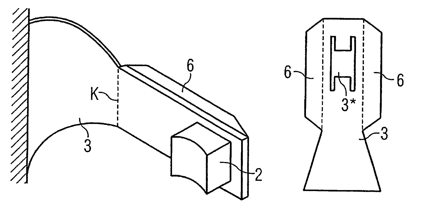
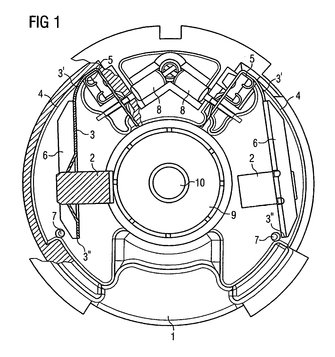
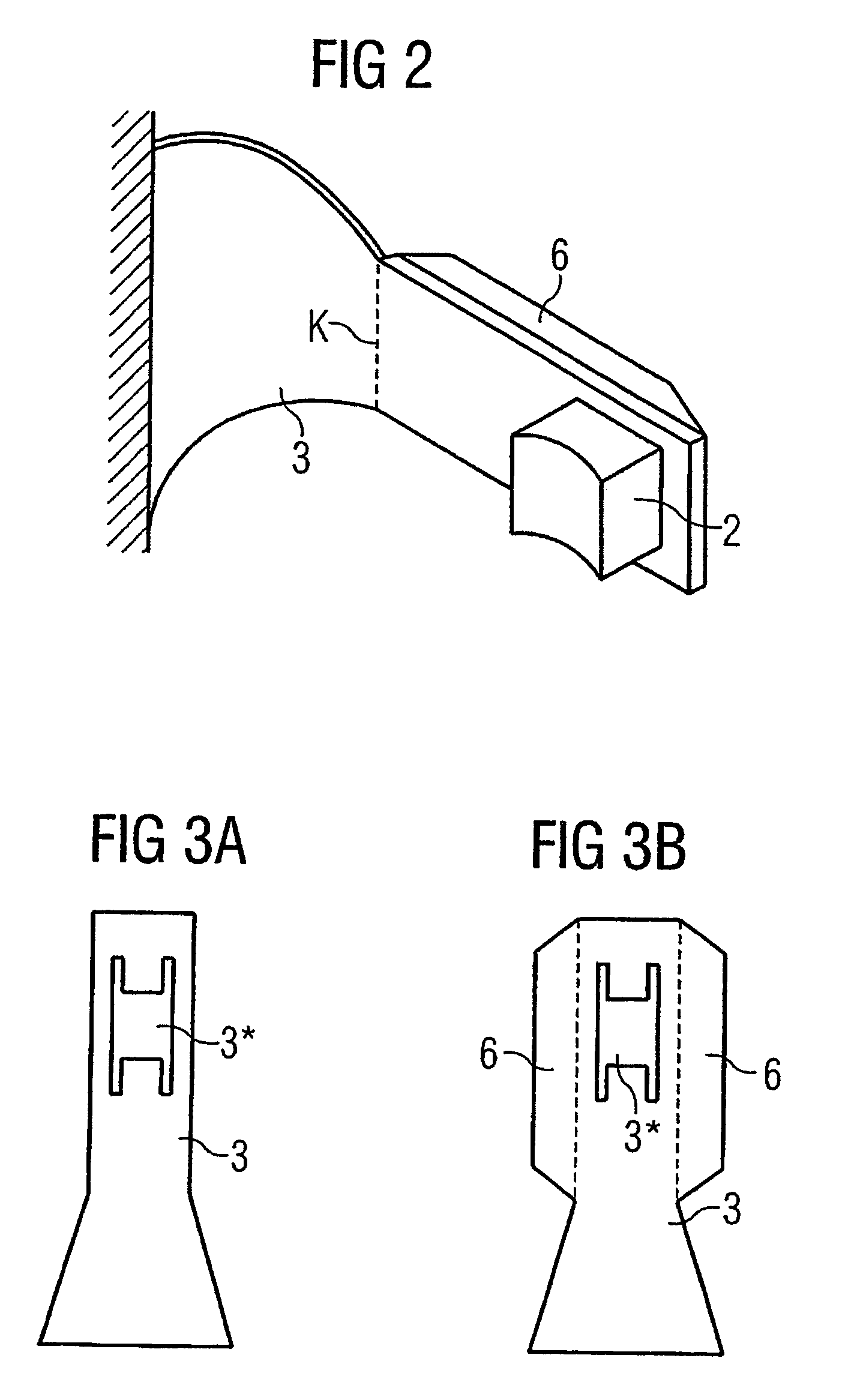
[0019]FIG. 1 shows a simplified schematic illustration of the plan view, partially in longitudinal section (hatched), of the mount part 1 for commutator brushes 2 of the electric motor. The commutator brushes 2 are in this case arranged on in each case one curved torsion spring 3 which has, in each case at their end 3′ which is remote from the commutator brush 2, a trapezoidal form (not illustrated) when developed. With its longest edge, which corresponds to the longest side of the trapezoid, each torsion spring 3 is clamped between an outer stop 4 and an inner stop 5. The outer stop 4 has a curvature which is at an angle with respect to the respective curved torsion spring 3. A plug sleeve is in each case arranged as the inner stop 5. This plug sleeve applies electrical power to the respective torsion spring 3. Each torsion spring 3 has, in the region of the respective commutator brush 2, a material reinforcement section 6 at its end which is remote from the commutator brush 2. Thi...


PUM


Abstract

The invention relates to a support element on which the commutator brushes are each disposed on one curved spiral spring each. Said spring, on its side facing away from the commutator brush in the area of the end of the coil is trapezoid and is braced between an outer stop and an inner stop with its longest edge that corresponds to the longest side of the trapezoid.

Description

CROSS REFERENCE TO RELATED APPLICATIONS[0001]The present application is a continuation of international application PCT / DE2003 / 003726, filed on 11 Nov. 2003, which designated the United States and was pending at the time of designation; and further claims priority to German patent application 10256831.6, filed Dec. 4, 2002; the both of which are herein incorporated by reference.BACKGROUND OF THE INVENTION[0002]The invention relates to a mount part for commutator brushes of an electric motor.[0003]The arrangement of commutator brushes for an electric motor is known. DE 101 12 427 A1 has disclosed an electromotive adjusting unit for a metering system of an internal combustion engine. In this case, the brush holder is in the form of a so-called hammer-type brush holder which has two electrically conducting leaf springs which each bear a commutator brush and protrude freely and which are, with one of their ends, injection-molded on a mount plate and are connected to electrical conductor...

Claims


Application Information

Patent Timeline
IPC IPC(8): H02K13/00H02K5/14H02K5/22H01R39/38H01R39/39
CPCH01R39/39H02K5/145H01R39/381
Inventor BENDER, GUENTHER
Owner CONTINENTAL AUTOMOTIVE GMBH
Why Eureka
Try Eureka