Micro-optical electromechanical device and method for manufacturing it

a micro-optical electromechanical and electromechanical technology, applied in piezoelectric/electrostrictive/magnetostrictive devices, optics, instruments, etc., can solve the problems of electrostatic drive being very inefficient for large amplitude excitation, and other limitations of electrostatic actuators when used in scanning mirrors

Active Publication Date: 2016-01-07
MURATA MFG CO LTD
View PDF3 Cites 10 Cited by
  • Summary
  • Abstract
  • Description
  • Claims
  • Application Information

AI Technical Summary

Benefits of technology

[0011]An object of the present invention is to provide a micro-optical electromechanical device structure that in a given component area dimension provides a large single movable mirror surface and large tilt angles for said mirror surface, and at the same time avoids or alleviates at least one problem of the conventional configurations. Various objects of the present invention are achieved with a micro-optical electromechanical structure, and a manufacturing method as described herein.
[0022]In some embodiments, the bending springs have two or more bending parts, providing flexibility in two or more directions.

Problems solved by technology

In addition to the high voltages needed, the electrostatic actuator has other limitations when used in scanning mirrors.
Electrostatic drive is thus very inefficient for large amplitude excitation.

Method used


Image

  • Micro-optical electromechanical device and method for manufacturing it
  • Micro-optical electromechanical device and method for manufacturing it
  • Micro-optical electromechanical device and method for manufacturing it

Examples


Embodiment Construction

[0036]The following embodiments are exemplary. Although the specification may refer to “an”, “one”, or “some” embodiment(s), this does not necessarily mean that each such reference is to the same embodiment(s), or that the feature only applies to a single embodiment. Single features of different embodiments may be combined to provide further embodiments.

[0037]In the following, features of the invention will be described with a simple example of a device architecture in which various embodiments of the invention may be implemented. Only elements relevant for illustrating the embodiments are described in detail. Various implementations of micro-optical electromechanical structures that are generally known to a person skilled in the art may not be specifically described herein.

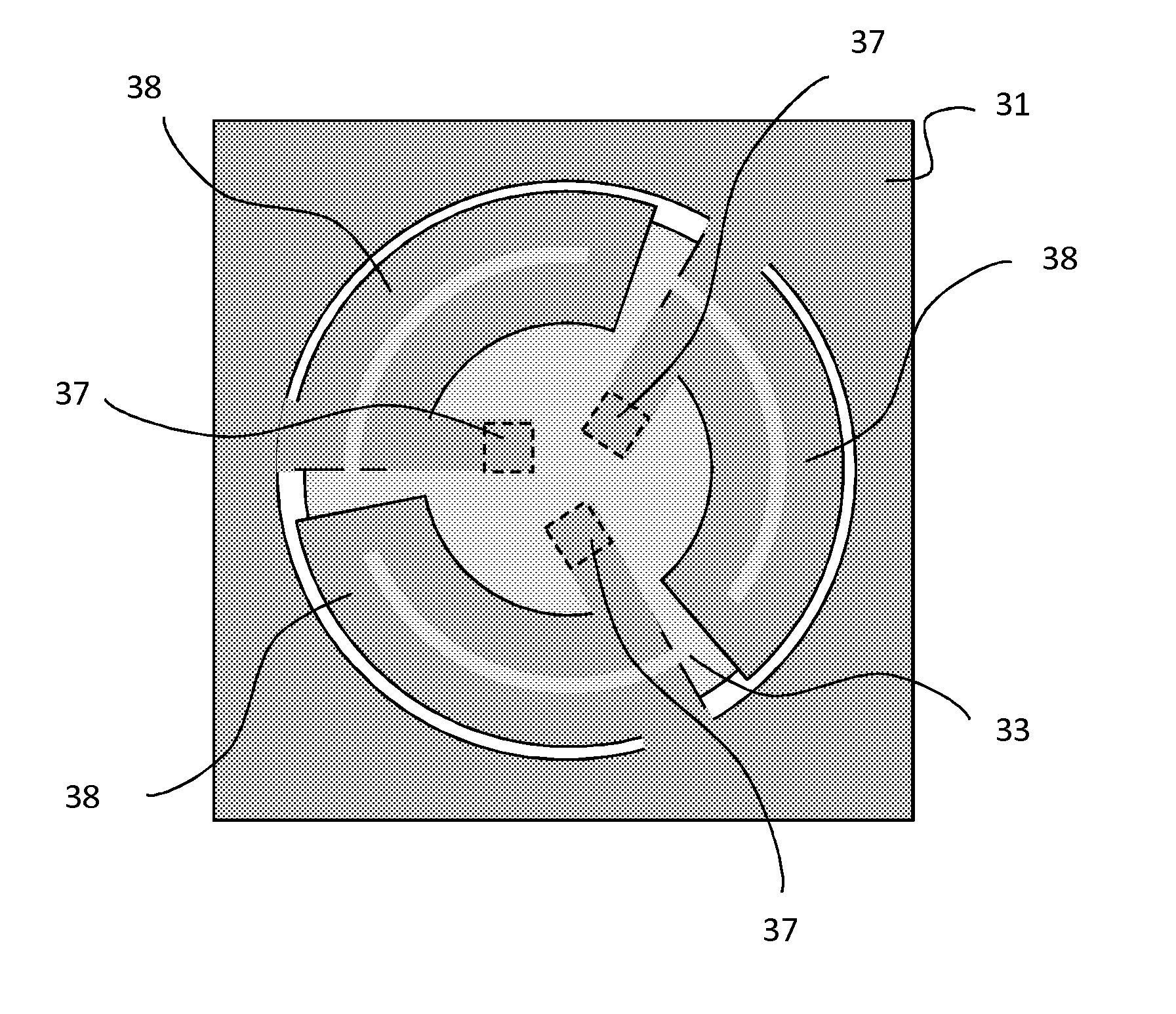
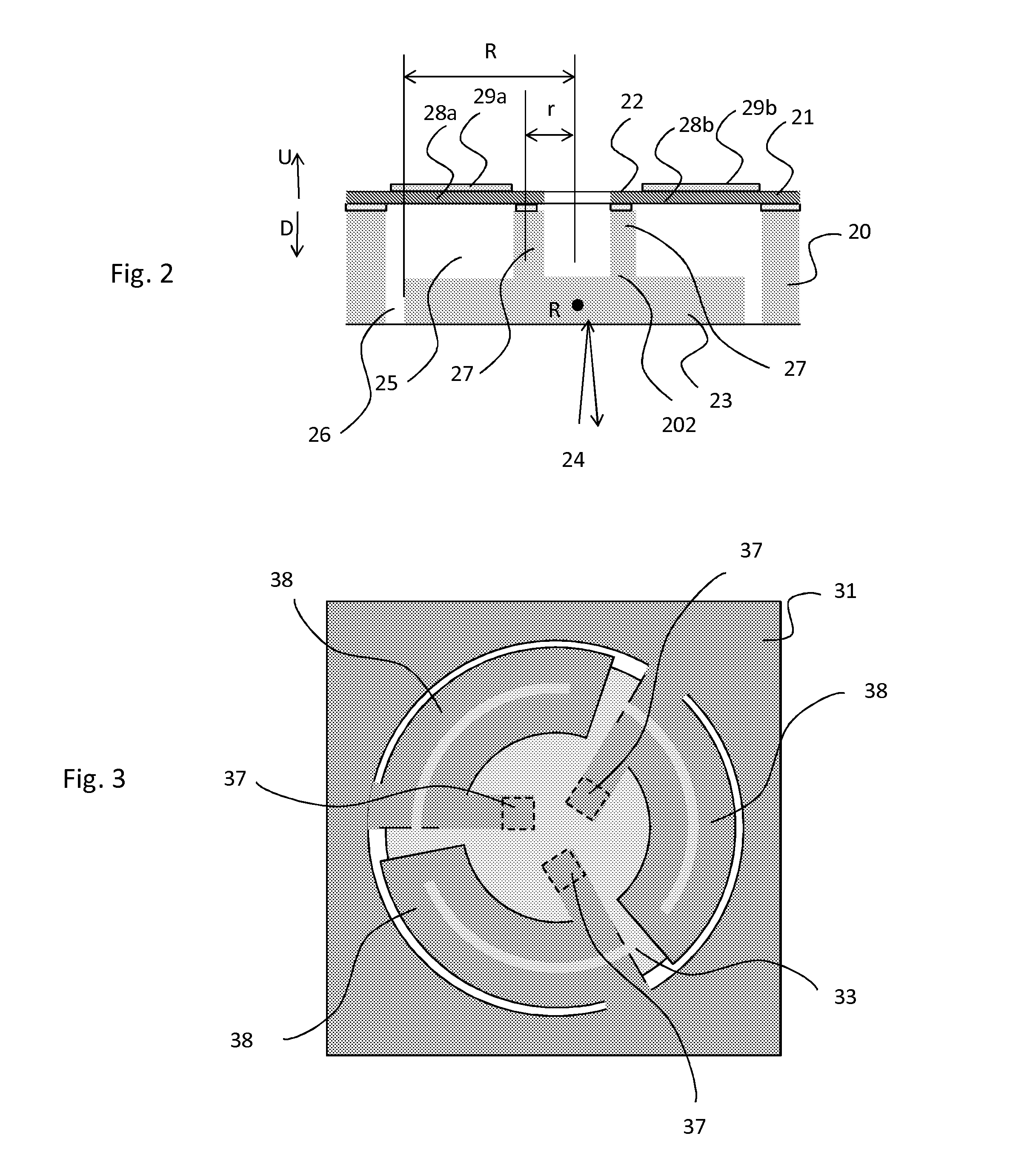
[0038]FIG. 2 illustrates an embodiment of an improved micro-optical electromechanical structure. A micro-optical electromechanical device includes a body 20, a mirror element 23, 27, and a spring structure 28a, 2...


PUM


Abstract

A micro-optical electromechanical device includes a body, a mirror element, and a spring structure configured to flexibly support the mirror element to the body. The spring structure includes at least one piezoelectric transducer adapted to induce in the spring structure a displacement that moves the mirror element.

Description

BACKGROUND[0001]1. Field[0002]The present invention relates to micro-optical electromechanical devices and especially to a micro-optical electromechanical device and a method for manufacturing a micro-optical electromechanical device, as defined in the preambles of the independent claims.[0003]2. Description of the Related Art[0004]Mirrors for reflecting a beam of light have been developed based on MEMS technologies. In a scanning mirror, the direction of reflection can be changed as a function of time. A scanning mirror can direct the light beam over a range of directions in one or two dimensions, and it may also be used to collect light from a range of directions with good angular accuracy and resolution. Scanning operation over an angular range is obtained by tilting the mirror to an angle and varying this angle as a function of time. Often this is done in a periodical or oscillating manner. To obtain high scanning angular amplitude the mirror may be operated in a resonant mode. ...

Claims


Application Information

Patent Timeline
Patent Type & Authority Applications(United States)
IPC IPC(8): G02B26/08G02B26/10H01L41/311H01L41/314
CPCG02B26/0858H01L41/311H01L41/314G02B26/10G02B26/101H10N30/071H10N30/074
Inventor KUISMA, HEIKKI
Owner MURATA MFG CO LTD
Why Eureka
Try Eureka