Lane Level Traffic

a traffic parameter and lane level technology, applied in the field of camera view traffic parameter calculation, can solve the problems of not providing exact and accurate traffic information, no traffic data can be easily extracted from video stream images, and the computing system may slow vehicles approaching congested areas

Active Publication Date: 2016-01-07
HERE GLOBAL BV
View PDF13 Cites 32 Cited by
  • Summary
  • Abstract
  • Description
  • Claims
  • Application Information

AI Technical Summary

Problems solved by technology

The sampling rates may vary (e.g., 10 out of 100 vehicles are detected) but do not provide exact and accurate traffic information.
However, no traffic data can be easily extracted from the

Method used


Image

  • Lane Level Traffic
  • Lane Level Traffic
  • Lane Level Traffic

Examples


Embodiment Construction

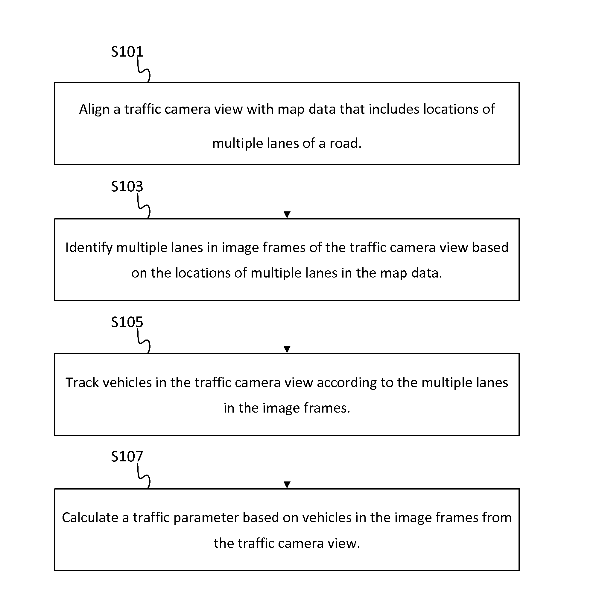
[0017]A traffic camera is a video camera that is positioned to record or transmit video data of a road and the vehicles traveling on the road. Traffic cameras may be useful to give a snapshot of the current traffic conditions of the road or to monitor for traffic conditions such as congestion, construction, or accidents. Typically, a user views the video stream and makes a conclusion on traffic conditions based on the visible traffic. However, no traffic data can be easily extracted from the video stream images. The following embodiments extract traffic data from the video stream and provide the traffic data in another type output.

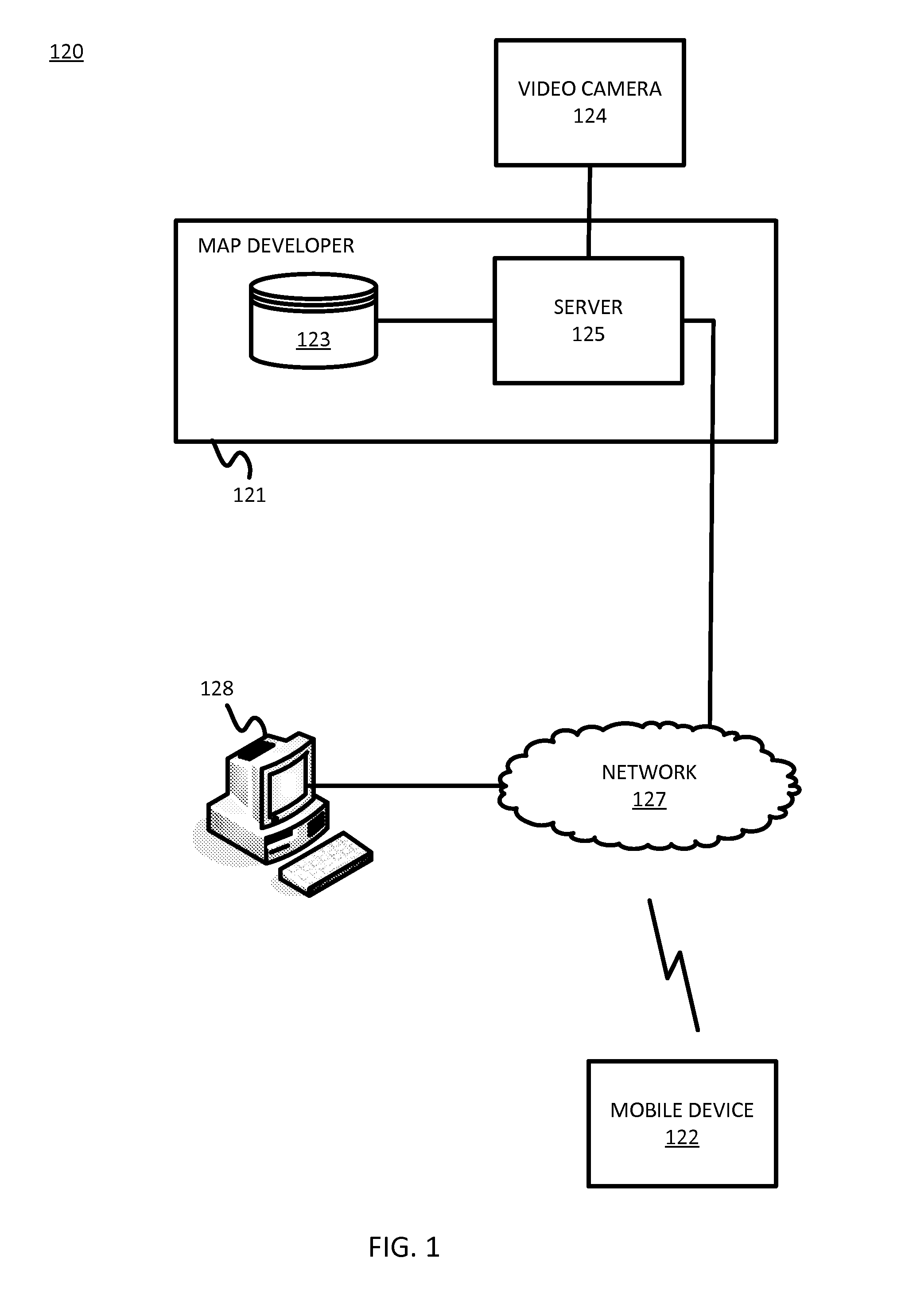
[0018]FIG. 1 illustrates an example system for lane level traffic designations. The system 120 includes a developer system 121, one or more mobile devices 122, a workstation 128, and a network 127. The system 120 may receive a video stream including traffic from video camera 124. Additional, different, or fewer components may be provided. For example, many...


PUM


Abstract

Lane level traffic levels are determined based on traffic camera images. A controller aligns a three-dimensional map with a traffic camera view, and identifies multiple lanes in the traffic camera view based on lane delineations of the three-dimensional map. The controller calculates a traffic parameter based on the multiple lanes in image frames from the traffic camera view and provides a traffic graphic based on the traffic parameter.

Description

FIELD[0001]The following disclosure relates to the calculation of a traffic parameter from a camera view, or more particularly, the calculation of lane level traffic parameters from the coordination of three dimensional map data with a camera view.BACKGROUND[0002]Traffic technology is the study of movement of vehicles on the roads. Analytical techniques may manage and track traffic information and derive travel times, guide driving behavior and optimize road infrastructure for cities. Traffic Message Channel (TMC) and other traffic services deliver traffic information to customers. Traffic incidents and traffic flow are reported through broadcasts. Traffic delays may be caused by one or more of congestion, construction, accidents, special events (e.g., concerts, sporting events, festivals), weather conditions (e.g., rain, snow, tornado), and so on.[0003]The traffic data is collected from probes. The probes may be individual drivers or detection equipment near the road. The individua...

Claims


Application Information

Patent Timeline
IPC IPC(8): G06K9/00G06T17/05G08G1/01
CPCG06K9/00791G06T17/05G08G1/0104G06V20/54G06V20/647G06V10/74G06Q50/30G06Q10/063G06V20/56
Inventor CHEN, XINMA, XIANGOSTROVSKIY, ROMANZHAO, TERENCE
Owner HERE GLOBAL BV
Why Eureka
Try Eureka