Method for manufacturing a circular wafer by polishing the periphery, including a notch or orientation flat, of a wafer comprising crystal material, by use of polishing tape
Active Publication Date: 2016-01-07
MIPOX
View PDF9 Cites 4 Cited by
- Summary
- Abstract
- Description
- Claims
- Application Information
AI Technical Summary
Benefits of technology
[0028]By the method for manufacturing a circular wafer of the present invention, the periphery, including the edge part or the bevel part, of the wafer can be machined with high precision, thereby preventing cracking of a wafer that has a thin profile (a thickness of 1 mm or less) or comprises a compound material. Furthermore, a circular wafer having a shape closer to complete
Problems solved by technology
However, due to the reduced thickness of wafers, minute chipping or
Method used
View moreImage
Smart ImageViewing Examples
Examples
 PUM
| Property | Measurement | Unit |
|---|---|---|
| Angle | aaaaa | aaaaa |
| Radius | aaaaa | aaaaa |
| Elasticity | aaaaa | aaaaa |
Abstract
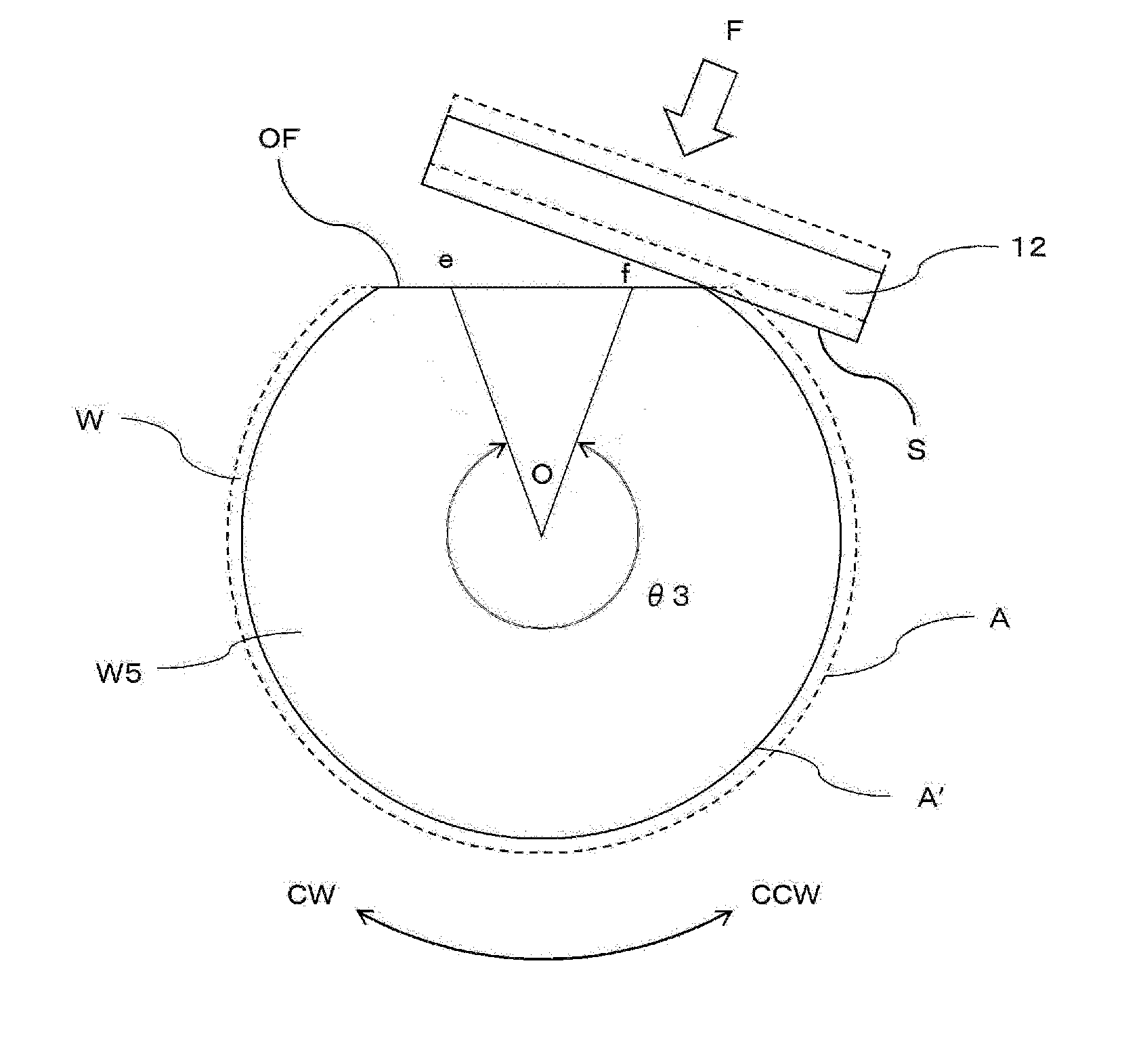
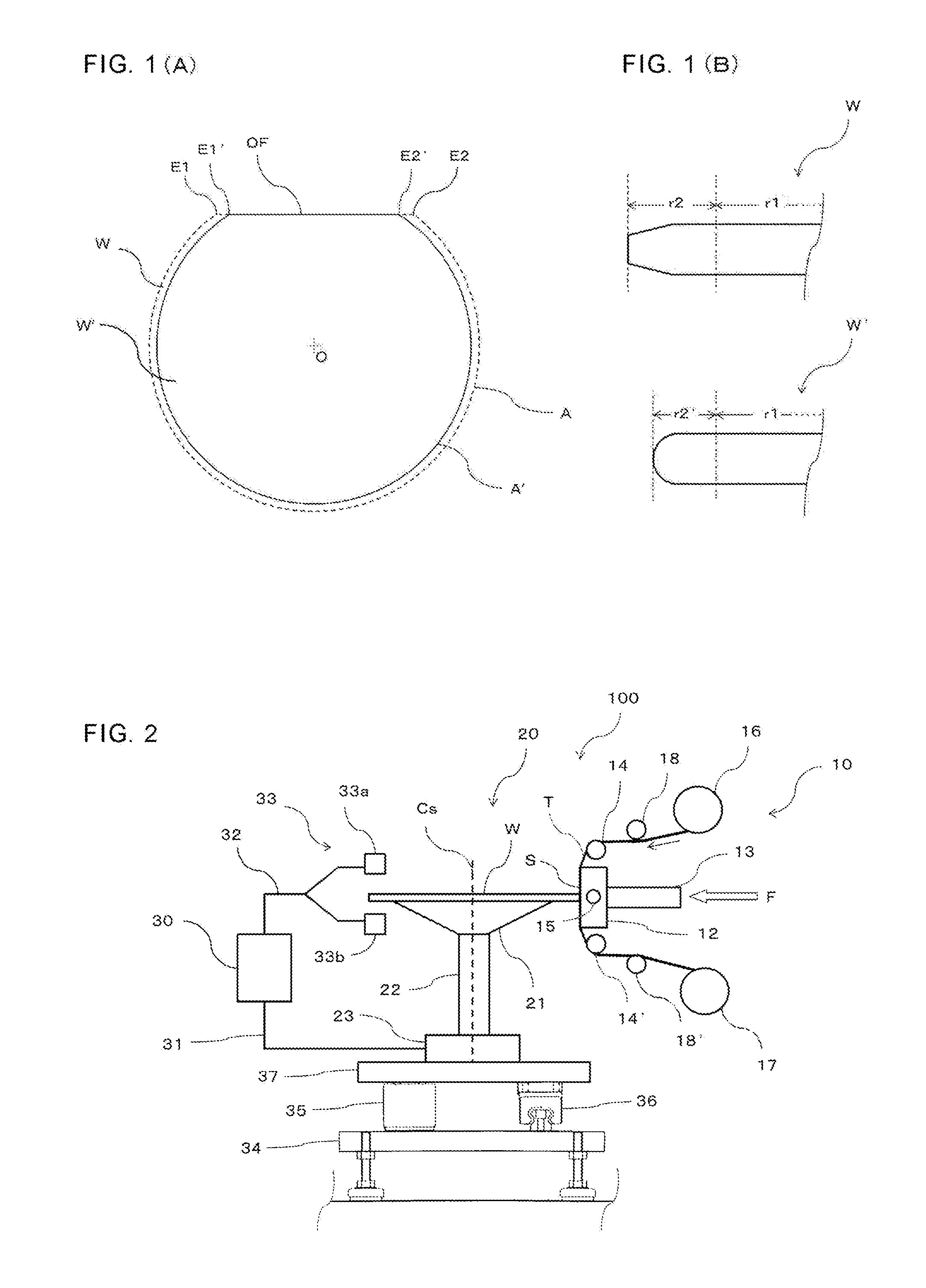
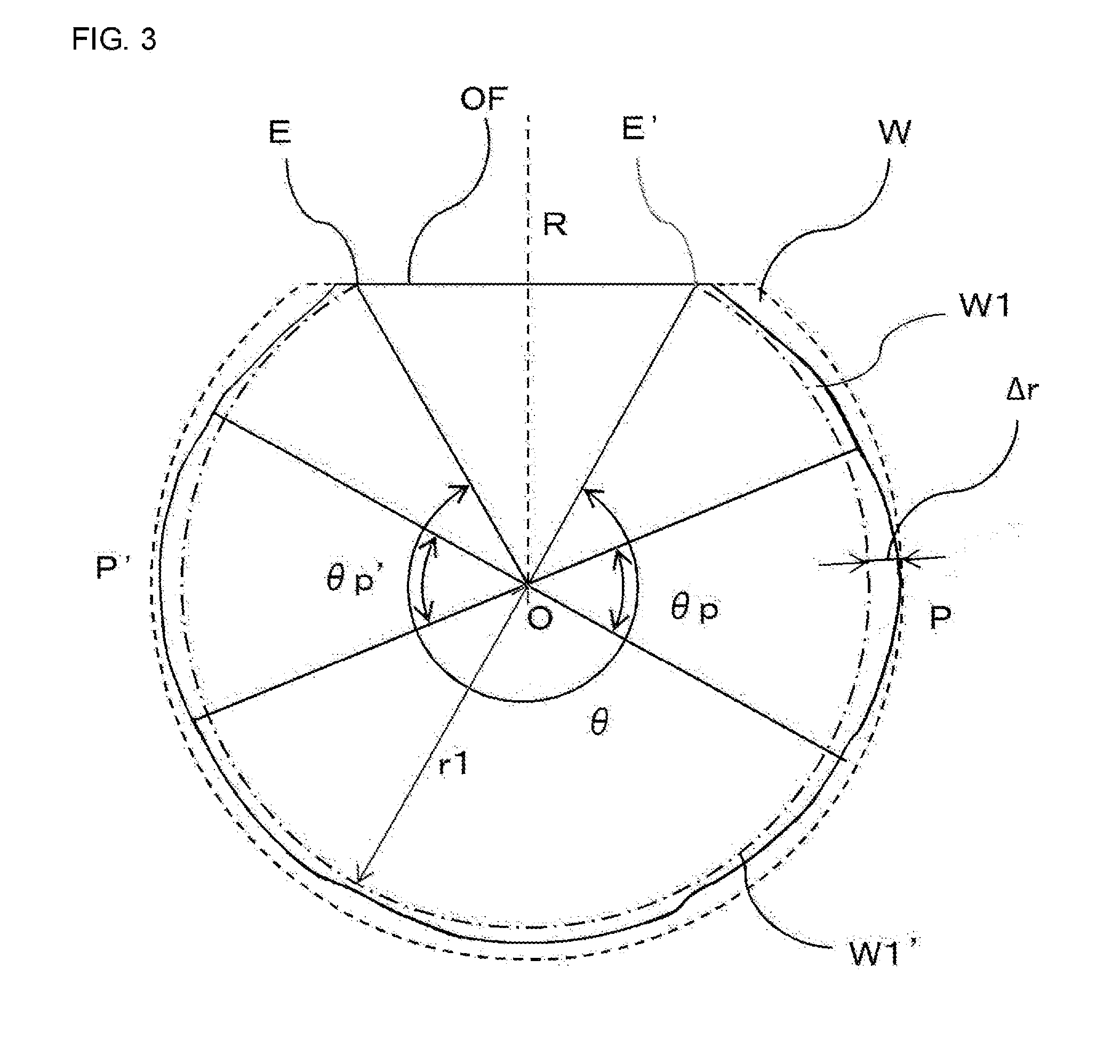
Provided is a method for producing a circular wafer using a grinding tape to grind the edge of a wafer comprising a crystalline material. A primary grinding step is provided for contacting a grinding body to the peripheral portion of a wafer placed centered on a horizontal stage and rotating the stage, thus grinding the peripheral portion. The radius of the wafer is measured, and a radius is set that is no greater than the measured smallest radius, and the difference Δr between the set radius and the measured wafer radius along the peripheral portion is determined. The portions of the peripheral portion at which Δr is greater than a predetermined value are determined and a secondary grinding step is provided for contacting the peripheral portion and the grinding body, rotating the stage forwards and backwards in a predetermined range of rotational angles, and grinding the peripheral portion.
Description
[0001]This application is a continuation of International application no. PCT / JP2014 / 050097 filed on Jan. 8, 2014 and claims the benefit of Japanese application no. 2013-025344 filed on Feb. 13, 2013, which are incorporated herein by reference in their entirety and for all purposes.TECHNICAL FIELD[0002]The present invention relates to a method for polishing the periphery of a wafer comprising crystal material. More particularly, the present invention relates to a method for manufacturing a circular wafer having improved handling properties by providing the periphery with excellent surface properties by use of a polishing tape.BACKGROUND ART[0003]In recent years, various kinds of wafers used in the manufacture of semiconductors, MEMS and the like have tend become thinner, with thicknesses between tens of micrometers to 1 mm, due to the increased density and the reduced thickness of circuit elements. A wafer is cut out from an ingot. Then the bevel part or edge part of the wafer is ch...
Claims
Login to View More Application Information
Patent Timeline
 IPC IPC(8): H01L21/02H01L21/306H01L21/66
CPCH01L21/02021H01L21/30625H01L22/20H01L22/12
Inventor YAMAGUCHI, NAOHIRO
Owner MIPOX
- R&D Engineer
- R&D Manager
- IP Professional
- Industry Leading Data Capabilities
- Powerful AI technology
- Patent DNA Extraction
Learn More Browse by: Latest US Patents, China's latest patents, Technical Efficacy Thesaurus, Application Domain, Technology Topic, Popular Technical Reports.
© 2024 PatSnap. All rights reserved.Legal|Privacy policy|Modern Slavery Act Transparency Statement|Sitemap|About US| Contact US: help@patsnap.com


