Drop in surgical illuminator

Active Publication Date: 2016-01-14
INVUITY
View PDF13 Cites 20 Cited by
  • Summary
  • Abstract
  • Description
  • Claims
  • Application Information

AI Technical Summary

Benefits of technology

[0008]The present application generally relates to medical devices, systems and methods, and more particularly relates to illumination of a surgical field in a patient. More specifically, the present application relates to anchoring an illumination element to, or adjacent the patien

Problems solved by technology

The device is not anchored and can easily move around and get in the way.
The patient must b

Method used


Image

  • Drop in surgical illuminator
  • Drop in surgical illuminator
  • Drop in surgical illuminator

Examples


Embodiment Construction

[0046]Specific embodiments of the disclosed device, delivery system, and method will now be described with reference to the drawings. Nothing in this detailed description is intended to imply that any particular component, feature, or step is essential to the invention.

[0047]Surgical illuminators are often coupled to a surgical instrument such as a retractor blade or retractor frame. FIG. 4 illustrates the illumination element 206 coupled to a retractor frame 202 having blades 204. An input cable 206 such as a fiber optic cable allows light to be input from an external source to the illumination element 206.

[0048]Thus, the surgical illuminator position is fixed relative to the surgical field and this can be inconvenient for a surgeon who may require illumination of the surgical field to be adjusted during surgery, or for the illuminator to be moved to a different position in the surgical field in order to accommodate surgical instruments or a surgeon's hands. Also, the retractors ar...


PUM


Abstract

An illumination system for adjustably positioning an illuminator in a surgical field in a patient includes an anchor element and an illumination element. The anchor element is configured to be releasably coupled with the patient, and the illumination element is coupled to the anchor element. The anchor element or the illumination element is configured to be coupled, uncoupled, and recoupled with the patient or adjacent surgical equipment. This allows repositioning of the illumination element at a plurality of positions in the surgical field without interfering with adjacent surgical instruments, and further permits adjustment of illumination in the surgical field.

Description

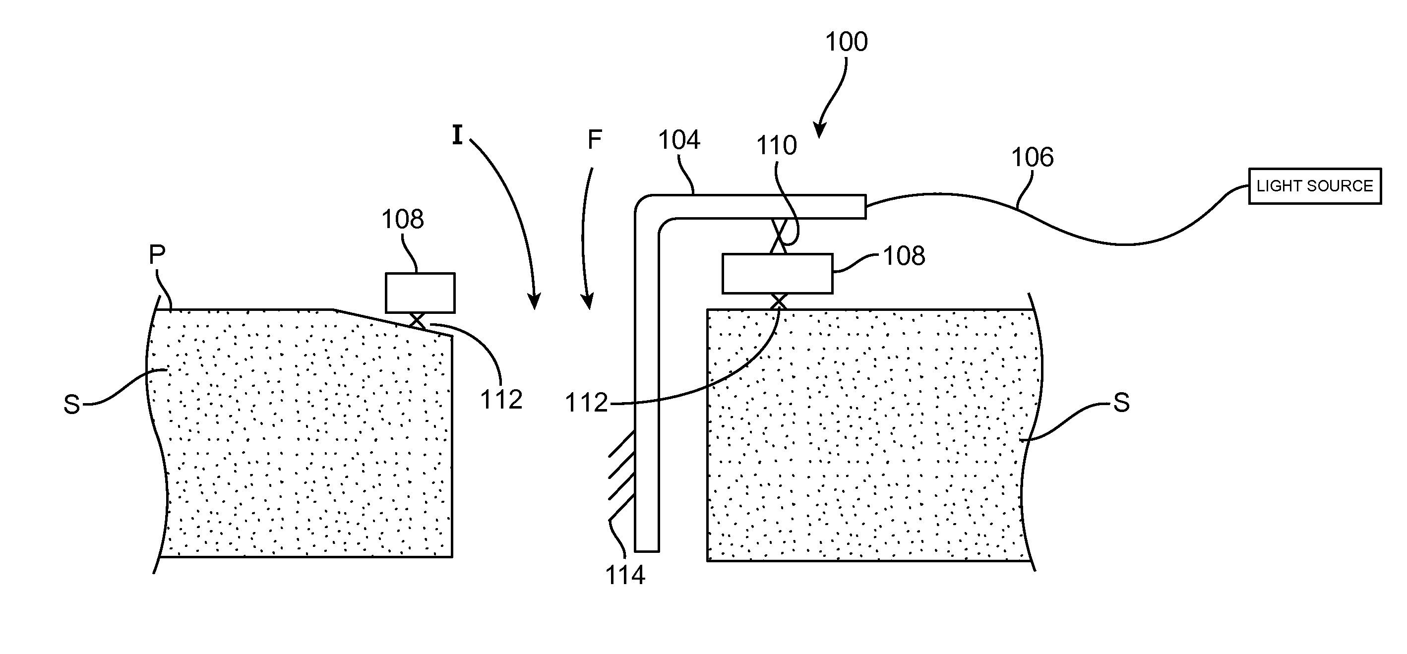
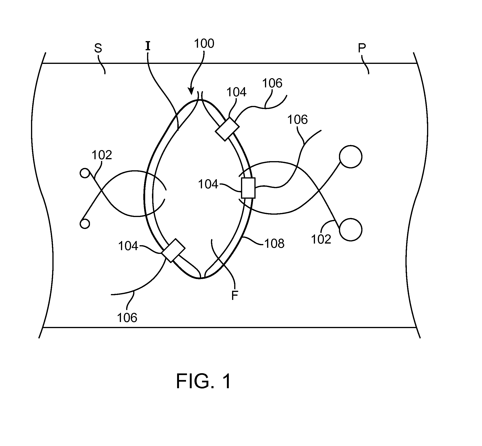
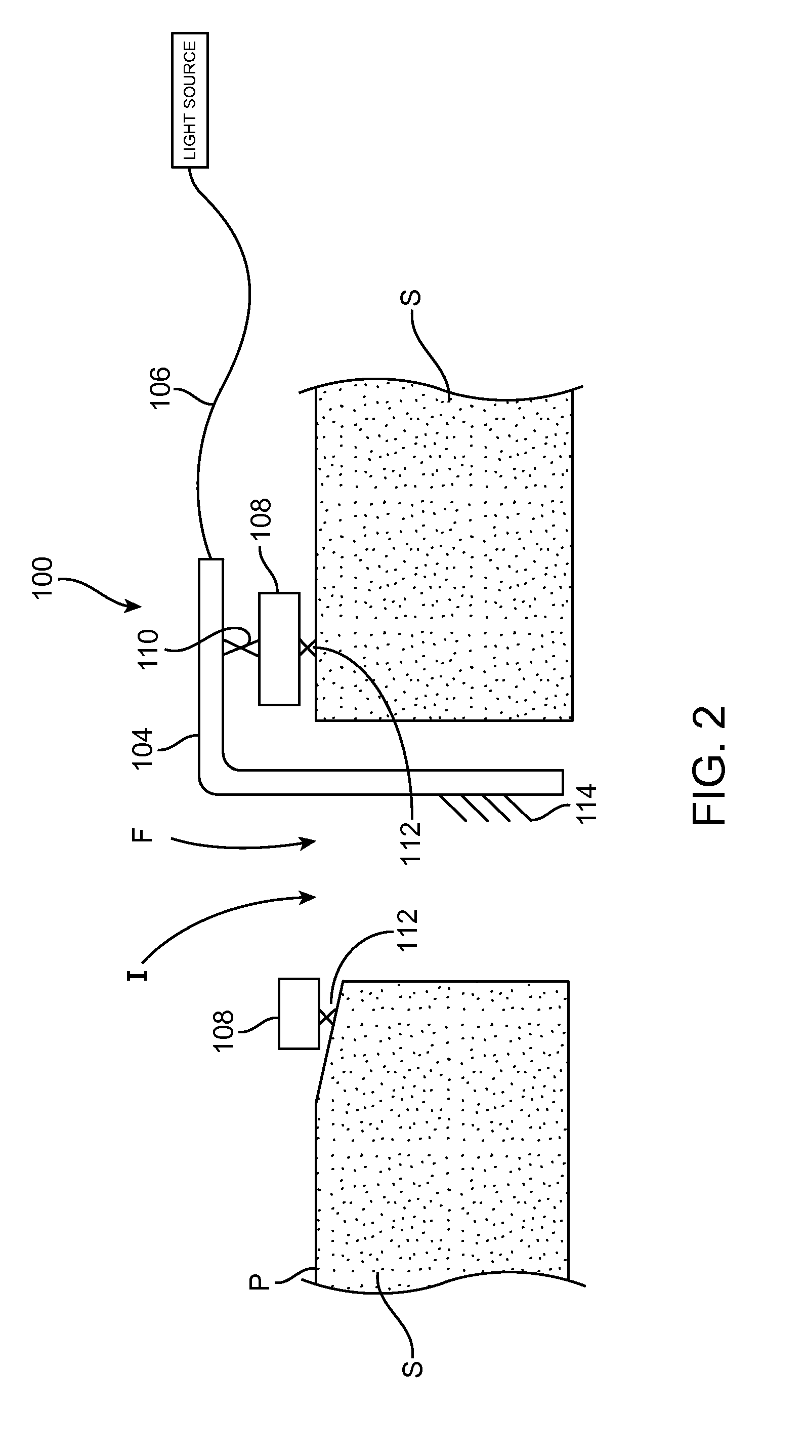
CROSS-REFERENCE TO RELATED APPLICATIONS[0001]The present application is a non-provisional of, and claims the benefit of U.S. Provisional Patent Application No. 61 / 932,652 (Attorney Docket No. 40556-732.101) filed Jan. 28, 2014; the entire contents of which are incorporated herein by reference.BACKGROUND OF THE INVENTION[0002]1. Field of the Invention[0003]The present application generally relates to medical devices, systems and methods, and more particularly relates to illumination of a surgical opening during a procedure. More specifically, the present application relates to anchoring of an illumination element to the tissue, surgical draping or other adjacent surgical equipment so that the illumination element is easily anchored to tissue or surgical drapes or other adjacent surgical equipment and preferably without requiring attachment to surgical instruments such as retractor blades. This allows the illumination element to be easily positioned and repositioned in the surgical fi...

Claims


Application Information

Patent Timeline
IPC IPC(8): A61B1/06A61B1/07A61B1/12A61B1/313A61B17/02
CPCA61B19/5202A61B17/0218A61B1/0684A61B1/07A61B19/08A61B1/128A61B2218/008A61B2017/00283A61B2017/00951A61B2017/00876A61B2017/00477A61B2217/005A61B1/3132A61B17/02A61B17/0206A61B2017/0287A61B90/57A61B90/30A61B2090/309A61B2090/306
Inventor VAYSER, ALEXRIMER, DOUGLASWAYNE, DAVID
Owner INVUITY
Why Eureka
Try Eureka