Actuatable flow conditioning apparatus

a flow conditioning and actuatable technology, applied in the direction of liquid fuel feeders, fluid removal, multi-phase mixers, etc., can solve the problems of multi-phase mixers, large compromises in mixer performance, accumulation of sand and other solid debris, etc., to facilitate solid debris cleaning, reduce slugging, and alter the operating envelope of the apparatus

Active Publication Date: 2016-01-14
ONESUBSEA IP UK LTD
View PDF3 Cites 9 Cited by
  • Summary
  • Abstract
  • Description
  • Claims
  • Application Information

AI Technical Summary

Benefits of technology

[0011]According to some embodiments, the apparatus is a mixer and is configured to be deployed upstream of a multiphase pump or any equipment that benefits from reduced slugging (e.g. compressors, multiphase flow meters, centrifugal separators, etc.). According to some embodiments, a lower annulus is formed between an outer lower portion of the inner vessel and an inner lower portion of the outer vessel. Actuating the inner vessel in the vertical direction can alter the size of the lower annulus, thereby altering an operating envelope of the apparatus. According to some embodiments, actuating the inner vessel upward facilitates cleaning of solid debris collected in the outer vessel for example by flushing into a dummy pump module.
[0012]According to some embodiments, the apparatus is a flow splitter positioned downstream of an outlet of a multiphase pump or wet gas compressor, etc. The apparatus can include a liquid-rich outlet from the outer vessel configured to draw liquid-rich flow from the multiphase fluid and to recirculate the liquid rich flow back into the multiphase pump. The lower annulus formed between inner vessel and a wall of the outer vessel can be reduced in size by actuation of the inner vessel, thereby increasing ability to draw liquid-rich fluid from the liquid-rich outlet.
[0013]According to some embodiments, a method of conditioning a multiphase fluid is described. The method includes: introducing the multiphase fluid from a source into an upper inlet of an outer vessel; flowing at least a portion of the multiphase fluid into an actuatable inner vessel disposed within the outer vessel through one or more upper openings at an upper location of the inner vessel; flowing at least a portion of the multiphase fluid through the inner vessel, outward through a lower opening of the inner vessel, and outward through a lower outlet of the outer vessel; and flowing a second portion of the multiphase fluid from the outer vessel through a lower annulus formed between an outer lower portion of the inner vessel and an inner lower portion of the outer vessel, and outward through the lower outlet of the outer vessel, thereby bypassing the inner vessel. According to some embodiments, the inner vessel is actuated in a vertical direction with respect to the outer vessel, thereby altering a size of the lower annulus. By actuating the inner vessel in an upward direction, the lower annulus is enlarged and solid debris collected in the outer vessel can be flushed outward through the annulus and outward through the lower outlet. According to some embodiments, the inner vessel is removed from the outer vessel, and accumulated solid debris is flushed from the outer vessel using an external fluid source. According to some embodiments, actuating the inner vessel in the vertical direction alters the size of the lower annulus, thereby altering an operating envelope of the mixing.
[0014]According to some embodiments, the multiphase fluid is split into a first flow path leading toward a surface location (or toward another downstream flow line) and a second liquid-rich flow path recirculating back into an upstream pump. Actuating the inner vessel in a vertical direction with respect to the outer vessel can close the lower annulus and cause most or all of the liquid phase to recirculate back into the upstream pump. Flow from one or more wells that had been previously non-producing can thus be initiated. When one or more of the wells are producing sufficient liquid phase, the inner vessel can be re-actuated, thereby re-opening the lower annulus.

Problems solved by technology

However, the larger the operating envelope, the greater the compromise in mixer performance.
Another challenge to multiphase mixers that are designed for long-term deployment is the accumulation of sand and other solid debris.
Yet another challenge in multiphase pumping stations is starting up a dead field.
There is hence a risk, when starting up a dead field where there are no free flowing wells.
No or limited amounts of liquid inside the station will reduce the available draw down and hence limit the ability to start a dead field.

Method used


Image

  • Actuatable flow conditioning apparatus
  • Actuatable flow conditioning apparatus
  • Actuatable flow conditioning apparatus

Examples


Embodiment Construction

[0025]The particulars shown herein are by way of example, and for purposes of illustrative discussion of the embodiments of the subject disclosure only, and are presented in the cause of providing what is believed to be the most useful and readily understood description of the principles and conceptual aspects of the subject disclosure. In this regard, no attempt is made to show structural details of the subject disclosure in more detail than is necessary for the fundamental understanding of the subject disclosure, the description taken with the drawings making apparent to those skilled in the art how the several forms of the subject disclosure may be embodied in practice. Further, like reference numbers and designations in the various drawings indicate like elements.

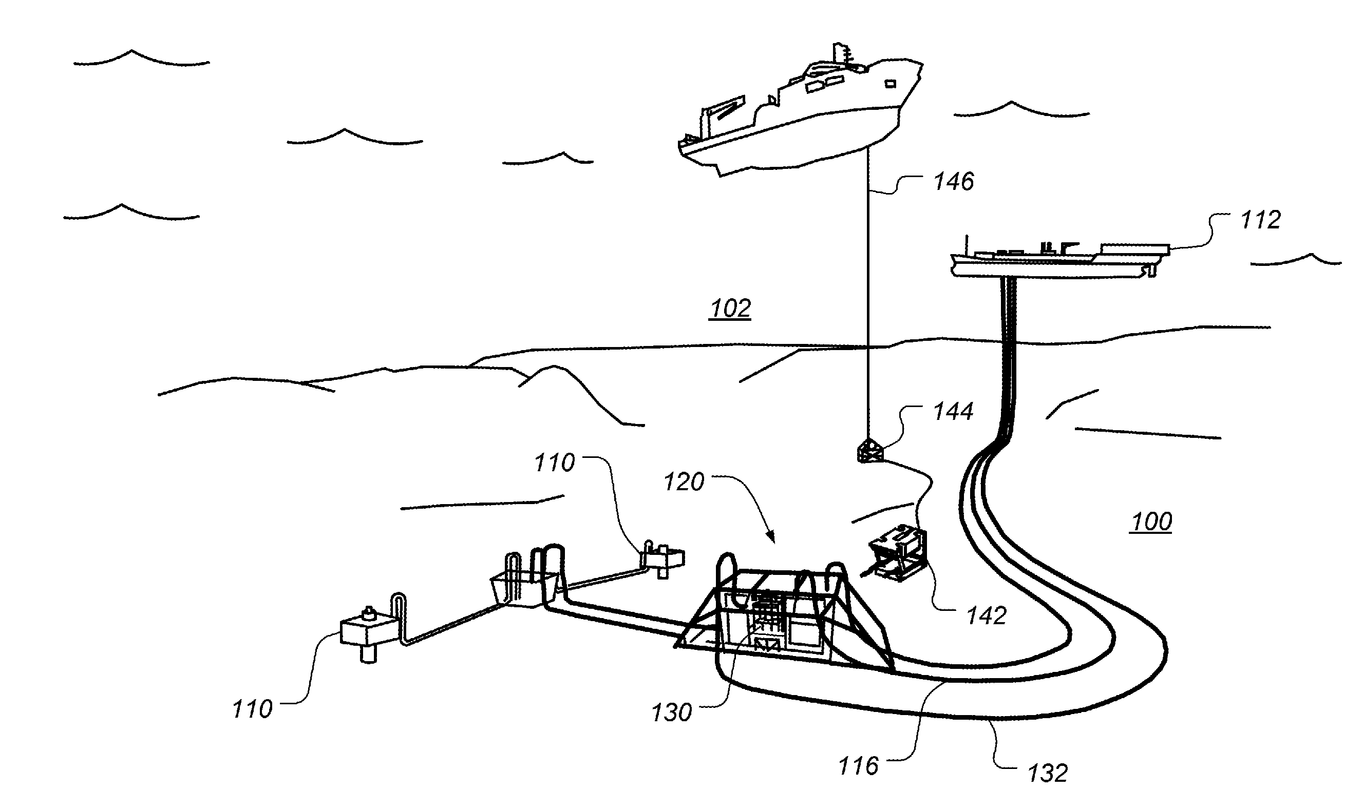
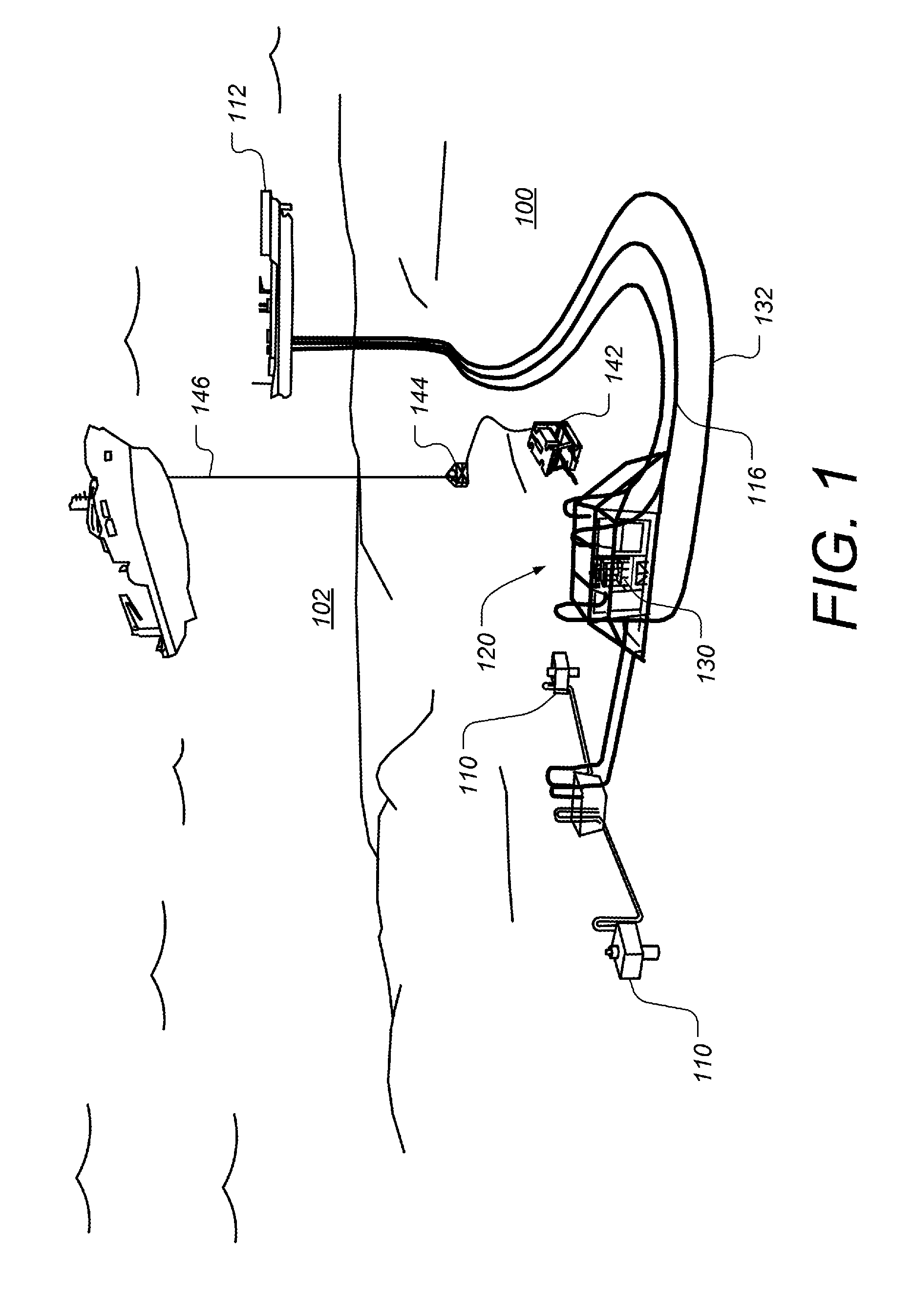
[0026]FIG. 1 is an example diagram illustrating a subsea environment in which a multiphase fluid processing system is deployed, according to some embodiments. On sea floor 100, a station 120 is that which is downstream ...


PUM

PropertyMeasurementUnit
sizeaaaaaaaaaa
volumeaaaaaaaaaa
flow rateaaaaaaaaaa

Abstract

An actuatable apparatus, such as a mixer or flow splitter, is described that forms part of a multiphase pumping station. An outer tank has an upper inlet and an actuatable inner vessel disposed within the outer vessel. Multiphase fluid can pass from the outer vessel into the inner vessel though large upper openings. The inner vessel is configured to be actuatable such that the inner vessel moves in a vertical direction, thereby altering the size of an annular opening between the bottom of the inner vessel and the outer vessel. In some cases, the annular opening is adjusted to alter the operating envelope of a mixer. In other cases, the annular opening is opened to allow for sand cleaning. In yet other cases the apparatus is a downstream flow splitter, and the annulus is shut off to prevent loss of liquid phase during the startup of a dead field.

Description

CROSS-REFERENCE TO RELATED APPLICATIONS[0001]Not applicable.STATEMENT REGARDING FEDERALLY SPONSORED RESEARCH OR DEVELOPMENT[0002]Not applicable.BACKGROUND[0003]1. Field of the Invention[0004]The present disclosure relates to fluid conditioning systems. More particularly, the present disclosure relates to systems for conditioning multiphase fluids, such as mixing and / or splitting such fluids in connection with a subsea and / or topside multiphase pumping system.[0005]2. Background of the Technology[0006]In fluid processing systems, such as multiphase pumping stations, a multiphase pump can be combined with an upstream multiphase mixer and downstream flow splitter. The multiphase mixer utilizes a large volume tank and it is advantageous to design the mixer for long-term installation on the sea floor. Because the multiphase mixer is often intended to be deployed for long periods of time, up to the lifetime of the field, it should be designed to deal with a relatively wide operating envel...

Claims


Application Information

Patent Timeline
Patent Type & Authority Applications(United States)
IPC IPC(8): B01F3/04E21B43/01
CPCB01F3/04985E21B43/01B01F23/2323B01F25/45211B01F35/1453B01F23/29
Inventor KANSTAD, STIG KAAREKANGAS, NILS EGIL
Owner ONESUBSEA IP UK LTD
Why Eureka
Try Eureka