Independent instrument landing system monitor

a technology of instrument landing system and monitor, which is applied in the direction of instruments, electrical/magnetic computing, analogue processes for specific applications, etc., can solve the problems of discontinuance of landing attempt, poor visibility, and most challenging tasks a pilot undertakes

Active Publication Date: 2016-01-14
HONEYWELL INT INC
View PDF5 Cites 9 Cited by
  • Summary
  • Abstract
  • Description
  • Claims
  • Application Information

AI Technical Summary

Benefits of technology

[0035]The system and method described herein will alert the crew that an automatically determined maneuver, based on received ILS signals, is not compatible with the actual intended course direction. The system and method provide onboard monitoring of the ILS signal quality by using a recorded statistical approach course to monitor the received ILS signal and to determine any disturbances outside of a predetermined magnitude.

Problems solved by technology

The approach to landing and touch down on the runway of an aircraft is one of the most challenging tasks a pilot undertakes during normal aircraft operations.
An approach outside of this envelope can result in an undesirable positioning of the aircraft with respect to the runway, resulting in a possible discontinuance of the landing attempt.
In some instances visibility may be poor during approach and landing operations, resulting in what is known as instrument flight conditions.
Though rare, there have been instances where an aircraft is taking off from the same runway that an aircraft is about to land, and temporarily interferes with the ILS signals.
This temporary interference can cause the ILS signals to be imbalanced.
If the imbalance is of a sufficient duration, it can cause the aircraft flight control / autopilot system to undergo and unneeded and undesirable maneuver.
In one particular documented case, the undesirable maneuver caused the aircraft to land on the left main landing gear only.

Method used


Image

  • Independent instrument landing system monitor
  • Independent instrument landing system monitor
  • Independent instrument landing system monitor

Examples


Embodiment Construction

[0017]The following detailed description is merely exemplary in nature and is not intended to limit the invention or the application and uses of the invention. As used herein, the word “exemplary” means “serving as an example, instance, or illustration.” Thus, any embodiment described herein as “exemplary” is not necessarily to be construed as preferred or advantageous over other embodiments. All of the embodiments described herein are exemplary embodiments provided to enable persons skilled in the art to make or use the invention and not to limit the scope of the invention which is defined by the claims. Furthermore, there is no intention to be bound by any expressed or implied theory presented in the preceding technical field, background, brief summary, or the following detailed description.

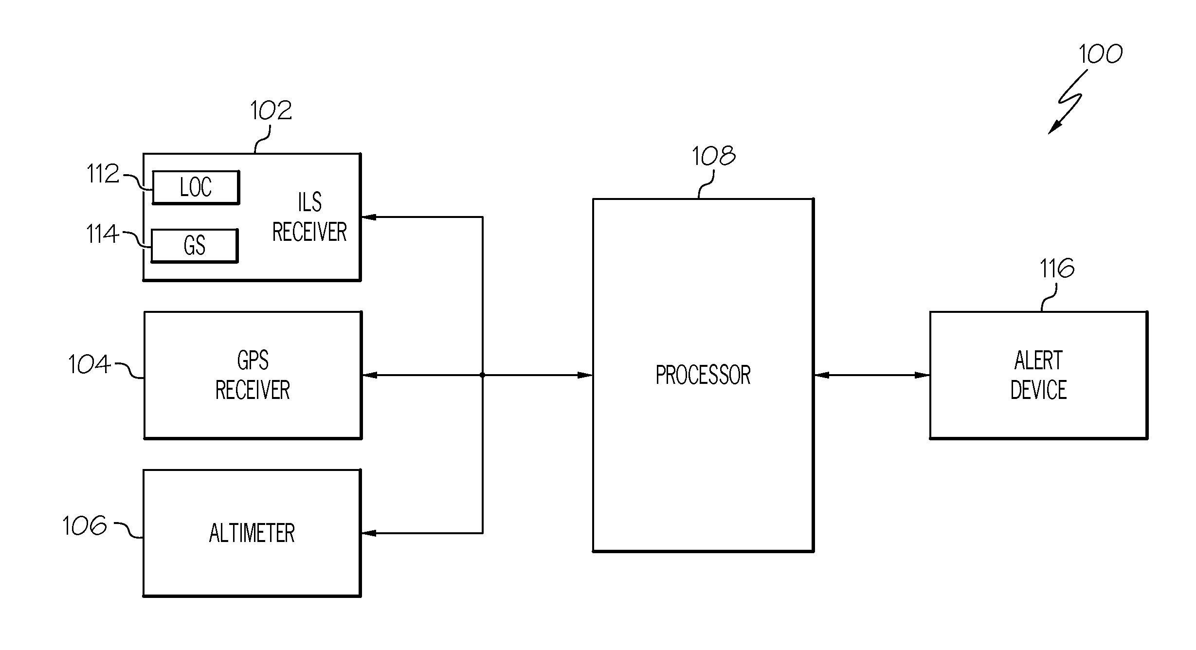
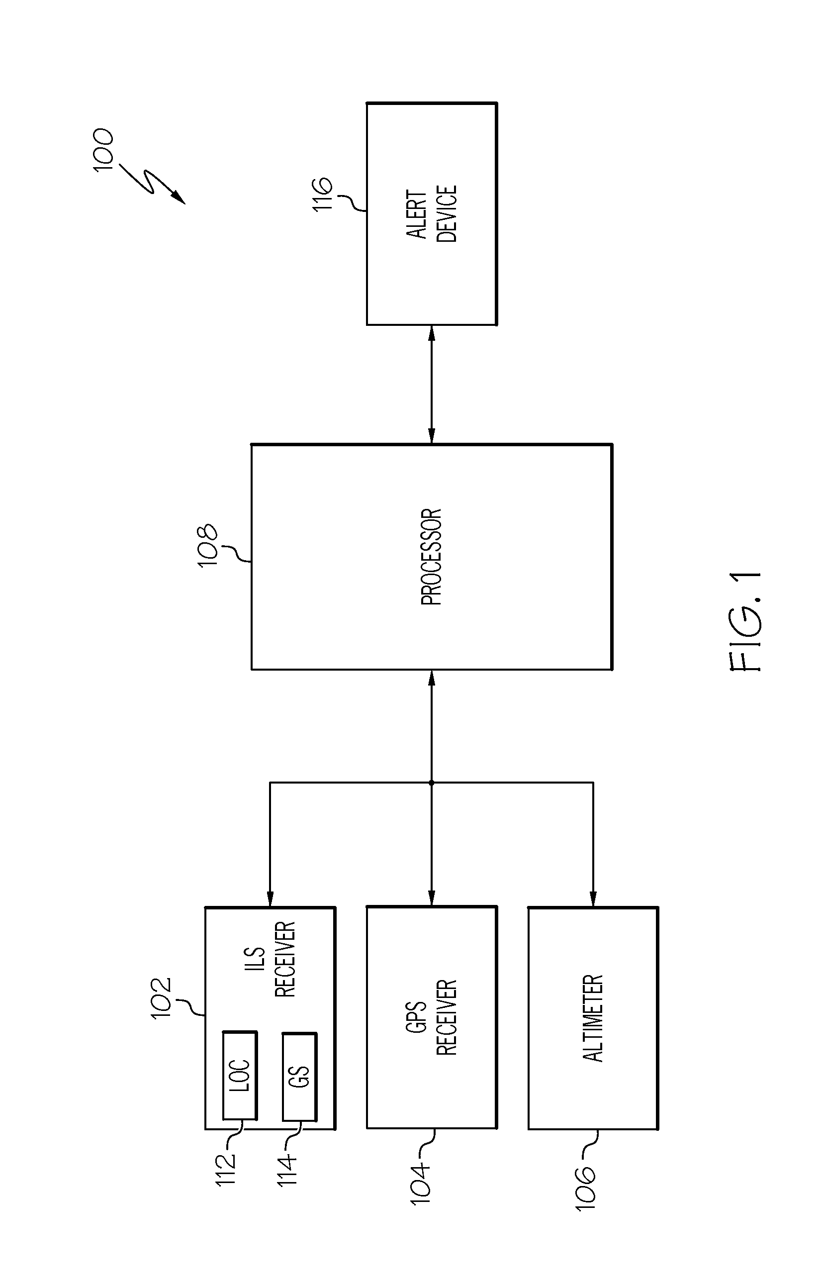
[0018]Referring first to FIG. 1, a functional block diagram of a portion of one embodiment of an aircraft avionics system 100 is depicted. The portion that is depicted is a system 100 for indep...


PUM


Abstract

A system and method of monitoring received instrument landing system (ILS) signals onboard an aircraft includes performing a pre-approach sampling of the received ILS signals to thereby generate pre-approach phase ILS data. A statistical approach course of the aircraft is determined based at least in part on the pre-approach phase ILS data. A determination is made as to when the aircraft is below a predetermined activation altitude and, when it is, approach sampling of the received ILS signals is performed to generate approach phase ILS data. The approach phase ILS data is compared to the statistical approach course to determine a course deviation. An alert signal is selectively generated when the course deviation exceeds a predetermined magnitude.

Description

TECHNICAL FIELD[0001]The present invention generally relates to aircraft instrument landing systems, and more particularly relates to an independent instrument landing system (ILS) monitor.BACKGROUND[0002]The approach to landing and touch down on the runway of an aircraft is one of the most challenging tasks a pilot undertakes during normal aircraft operations. To perform the landing properly, the aircraft approaches the runway within an envelope of attitude, course, speed, and rate of descent limits. The course limits include, for example, both lateral limits and glide slope limits. An approach outside of this envelope can result in an undesirable positioning of the aircraft with respect to the runway, resulting in a possible discontinuance of the landing attempt.[0003]In some instances visibility may be poor during approach and landing operations, resulting in what is known as instrument flight conditions. During instrument flight conditions, pilots rely on instruments, rather tha...

Claims


Application Information

Patent Timeline
Patent Type & Authority Applications(United States)
IPC IPC(8): B64D45/04G08G5/02G01S19/15G01S19/42
CPCG08G5/02B64D45/04G01S19/42G01S19/15G01S1/022G01S1/024G01S1/14
Inventor KOUKOL, ONDREJHE, GANGINNOCENT, SIMON
Owner HONEYWELL INT INC
Why Eureka
Try Eureka