
Liquid crystal reflective displays

a technology of reflective displays and liquid crystals, applied in non-linear optics, diffusing elements, instruments, etc., can solve the problem that the rubbing step is not compatible with conventional clean room processing techniques

Inactive Publication Date: 2006-03-07
QINETIQ LTD
View PDF14 Cites 0 Cited by
  • Summary
  • Abstract
  • Description
  • Claims
  • Application Information

AI Technical Summary

Benefits of technology

[0006]The present invention concerns devices using a rear mirror, either a totally or a partly reflecting mirror. Present mirrors may be formed by evaporating or spraying a reflective layer of e.g. aluminium on the rear outer wall of the cell. To form a diffuse specular reflector, it is standard to abrade the rear wall to roughen the surface prior to deposition of a reflective layer. Such an abrading step is not compatible with conventional clean room processing techniques.

Problems solved by technology

Such an abrading step is not compatible with conventional clean room processing techniques.

Method used


Image

  • Liquid crystal reflective displays
  • Liquid crystal reflective displays
  • Liquid crystal reflective displays

Examples


Embodiment Construction

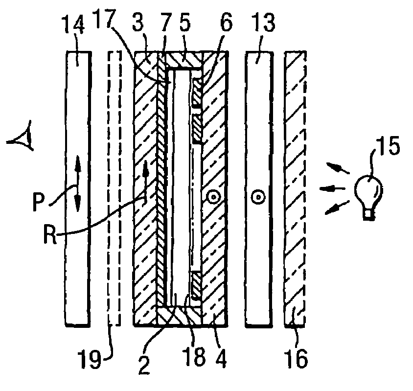
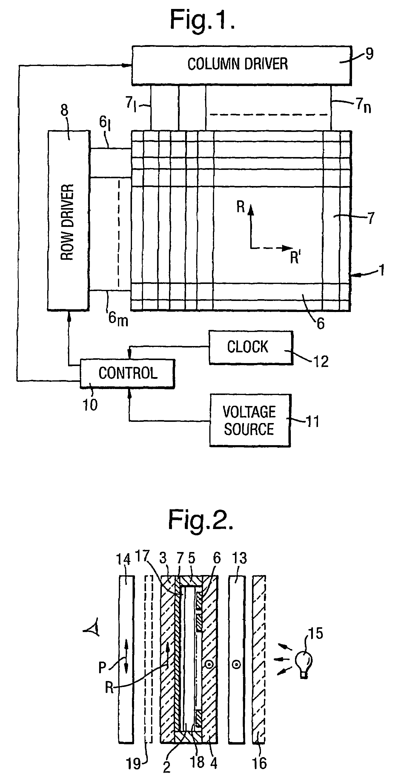
[0022]The display in FIGS. 1, 2 comprises a liquid crystal cell 1 formed by a layer 2 of nematic or long pitch cholesteric liquid crystal material contained between glass walls 3, 4. A spacer ring 5 maintains the walls typically 3–12 μm apart. Additionally numerous beads of the same dimensions may be dispersed within the liquid crystal to maintain an accurate wall spacing. Strip like row electrodes 6 e.g. of SnO2 or ITO (Indium Tin Oxide) are formed on one wall 3 and similar column electrodes 7 are formed on the other wall 4 in a known manner. With m-row and n-column electrodes this forms an m×n matrix of addressable elements or pixels. Each pixel is formed by the intersection of a row and column electrode. The electrodes are covered with a thin layer 17 of polymer e.g. polyimide, which has been rubbed to give alignment to the liquid crystal material 2. For twisted nematic devices the alignment directions on the two walls are approximately orthogonal.

[0023]A row driver 8 supplies vo...


PUM

PropertyMeasurementUnit
thicknessaaaaaaaaaa
thicknessaaaaaaaaaa
thicknessaaaaaaaaaa

Abstract

In a liquid crystal reflecting device comprising a cell (1) formed by two cell walls (3, 4) spaced apart by spacers (5) to contain a layer (2) of a liquid crystal material, electrode structures (6, 7) on the inner faces of the walls, and a surface alignment on one or both walls to align the liquid crystal material, a diffuse specular reflector is provided by a mirror base layer (21) formed by at least two different materials that are at least partly immiscible relative to one another forming a rough surface onto which a reflective layer (22) is coated. The mirror base layer (21) is formed by at least two different polymer and / or monomer materials that are at least partly immiscible relative to one another. The reflector layer (22) may be a single sheet, formed into a plurality of separate reflector elements, or patterned into electrodes.

Description

BACKGROUND OF THE INVENTION[0001]This invention relates to liquid crystal reflective displays.DESCRIPTION OF THE RELATED ART[0002]Typically liquid crystal displays comprise a cell formed by two glass walls spaced apart to contain a thin layer of a liquid crystal material. Electrode structures are formed on the surface of the walls, for example the electrodes may be in the form of strips electrodes forming row and columns giving a matrix of addressable pixels at the intersections of each row and column. The display may be addressed a row at a time in a known multiplex manner.[0003]The liquid crystal material may be nematic or long pitch cholesteric to form conventional 90° twisted nematic or super twisted nematic devices (270° twist as in U.S. Pat. No. 4,596,446), cholesteric to form phase change devices, and smectic material to form ferroelectric devices. Typical ferroelectric devices include the surface stabilised devices (SSFLCD) giving bistable devices. Such ferroelectric display...

Claims


Application Information

Patent Timeline
Patent Type & Authority Patents(United States)
IPC IPC(8): G02F1/1335G02B5/02
CPCG02F1/133553G02F1/133504
Inventor BANNISTER, ROBERT WILLIAMHEATH, RYAN MICHAELTUFFIN, RACHEL PATRICIA
Owner QINETIQ LTD
Learn More