
Server rack system

Active Publication Date: 2013-05-30
INVENTEC CORP
View PDF14 Cites 6 Cited by
  • Summary
  • Abstract
  • Description
  • Claims
  • Application Information

AI Technical Summary

Benefits of technology

The patent simplifies the process of replacing parts in a server rack system. When a new part is installed, the system automatically checks if the new part's firmware matches the hardware it's installed with. If not, the system automatically updates the firmware to make it compatible with the new part. This makes it easier to install new parts and ensures that the server rack system runs smoothly.

Problems solved by technology

If the version of the installed firmware does not match the device (for example, after replacement of device, the firmware corresponding to the newly installed device is always of an older version), the problem that the firmware is not compatible with the device is occurred.
Therefore, it is required to install or update the firmware of each device manually, resulting in the problem that the process is time consuming and it is easy to install firmware of an incompatible version.

Method used


Image

  • Server rack system
  • Server rack system
  • Server rack system

Examples


first embodiment

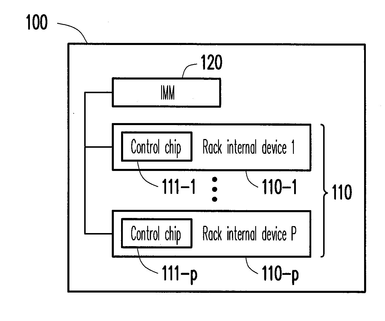
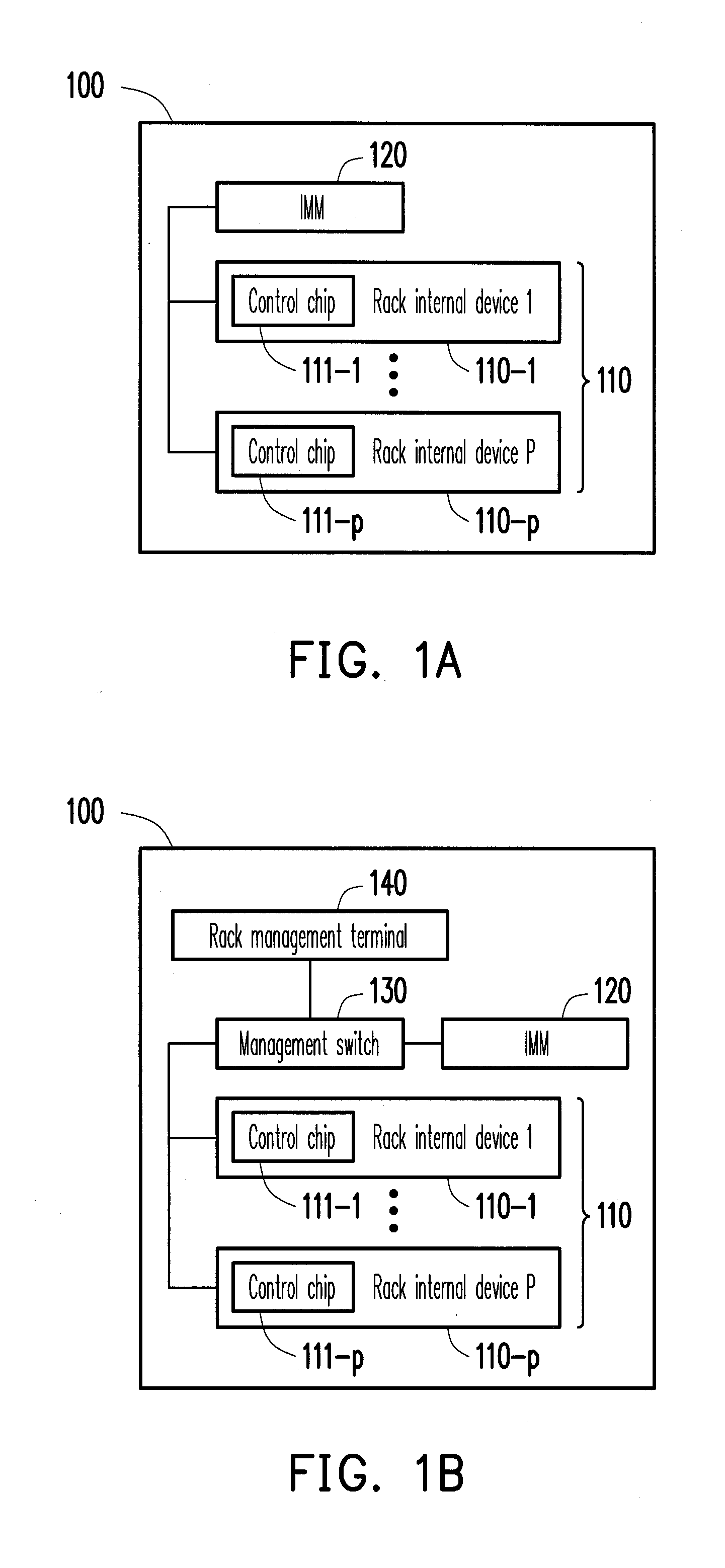
[0023]FIG. 1A to FIG. 1B are block diagrams of a server rack system according to a first embodiment of the present invention. In this embodiment, the server rack system 100 includes p rack internal devices 110 (110-1 to 110-p) and an IMM 120, where p is a positive integer greater than 1.

[0024]Referring to FIG. 1A, each rack internal device 110-1 to 110-p at least includes one of control chips 111-1 to 111-p. The IMM 120 is respectively coupled to the control chips 111-1 to 111-p. Moreover, the rack internal device 110 includes a plurality of servers. For example, the p rack internal devices have n servers, where n is a positive integer greater than 1 and less than p.

[0025]The IMM 120 is respectively coupled to the control chips 111-1 to 111-p. The IMM 120 is mainly used for managing the state of the rack internal devices 110-1 to 110-p in the server rack system 100. Moreover, the IMM 120 is further used for managing power up and power down of all the rack internal devices 110. For e...

second embodiment

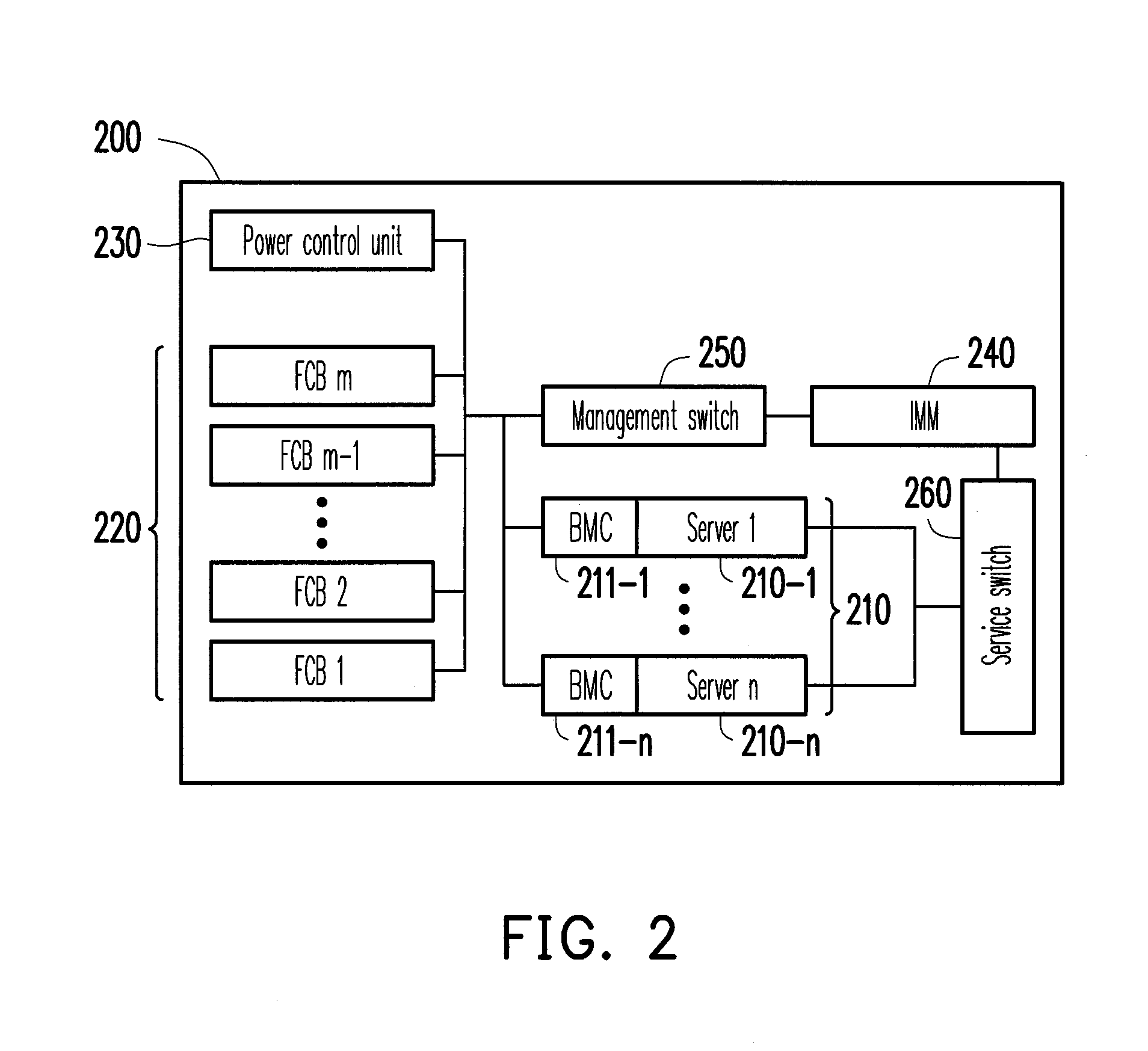
[0034]FIG. 2 is a block diagram of a server rack system according to a second embodiment of the present invention. Referring to FIG. 2, in this embodiment, the server rack system 200 includes n servers 210 (210-1 to 210-n), m FCBs 220, a power control unit 230, an IMM 240, a management switch 250, and a service switch 260. Herein, the servers 210 each include a BMC 211-1 to 211-n.

[0035]Herein, the IMM 240 is coupled to the BMCs 211-1 to 211-n, the FCB 220, and the power control unit 230 through the management switch 250. The IMM 240 is mainly used for managing the state of rack internal devices in the server rack system 200, namely, the state of the servers 210, the FCB 220 and the power control unit 230. Moreover, the IMM 240 is further used for managing power up and power down of all the servers 210. In addition, the IMM 240 assigns an MAC address for each of the BMCs 211-1 to 211-n through the management switch 250.

[0036]For example, an interface between the IMM 240 and the FCB ...


PUM


Abstract

A server rack system module is provided. Each rack internal device at least includes a control chip, and the rack internal devices include a plurality of servers. An integrated management module (IMM) is respectively coupled to the control chips, where the IMM stores integrated management firmware, and the integrated management firmware has latest version firmware of the control chip integrated therein and records latest version serial numbers of the latest version firmware. When the server rack system is started, the IMM reads a current version serial number of currently installed firmware of each control chip, and compares the current version serial number with the corresponding latest version serial number, so as to determine whether to update the currently installed firmware.

Description

CROSS-REFERENCE TO RELATED APPLICATION[0001]This application claims the priority benefit of China application serial no. 201110383868.0, filed on Nov. 28, 2011. The entirety of the above-mentioned patent application is hereby incorporated by reference herein and made a part of this specification.BACKGROUND OF THE INVENTION[0002]1. Field of the Invention[0003]The present invention generally relates to a server architecture, in particular, to a. server rack system that can automatically update firmware.[0004]2. Description of Related Art[0005]Presently, servers are widely used in enterprises, and in addition to the application in combination of the Internet and the telecommunications, the application range has expanded into the lives of ordinary people, such as finance and economics, online banking, and use of online credit cards. All the applications rely on the powerful computing capability of the server to ensure that the information is highly confidential and cannot be easily crac...

Claims


Application Information

Patent Timeline
IPC IPC(8): G06F9/44
CPCG06F8/65H04L41/082
Inventor WANG, HAO-HAO
Owner INVENTEC CORP
Learn More