Manufacturing method of a cable connector assembly

a manufacturing method and cable connector technology, applied in the manufacturing of contact parts, coupling device details, coupling device connections, etc., can solve the problems of affecting the adhesion of the outer boot, and achieve the effect of improving the step of stably forming a strain reli

Active Publication Date: 2016-01-14
FOXCONN INTERCONNECT TECH LTD
View PDF9 Cites 12 Cited by
  • Summary
  • Abstract
  • Description
  • Claims
  • Application Information

AI Technical Summary

Benefits of technology

[0007]An object of the present invention is to provide a manufacturing method of a cable connector assembly including an improved step of stably forming a strain relief thereof.

Problems solved by technology

This unevenness will affect adhesion of the outer boot to the strain relief.

Method used


Image

  • Manufacturing method of a cable connector assembly
  • Manufacturing method of a cable connector assembly
  • Manufacturing method of a cable connector assembly

Examples


Embodiment Construction

[0019]Reference will now be made in detail to the preferred embodiment of the present invention.

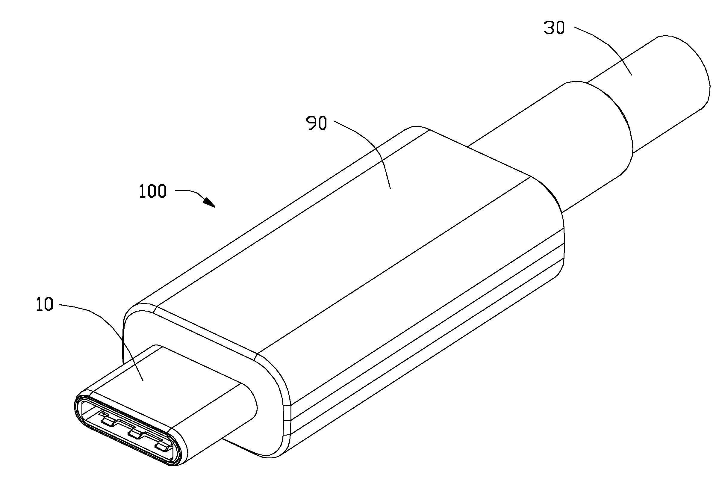
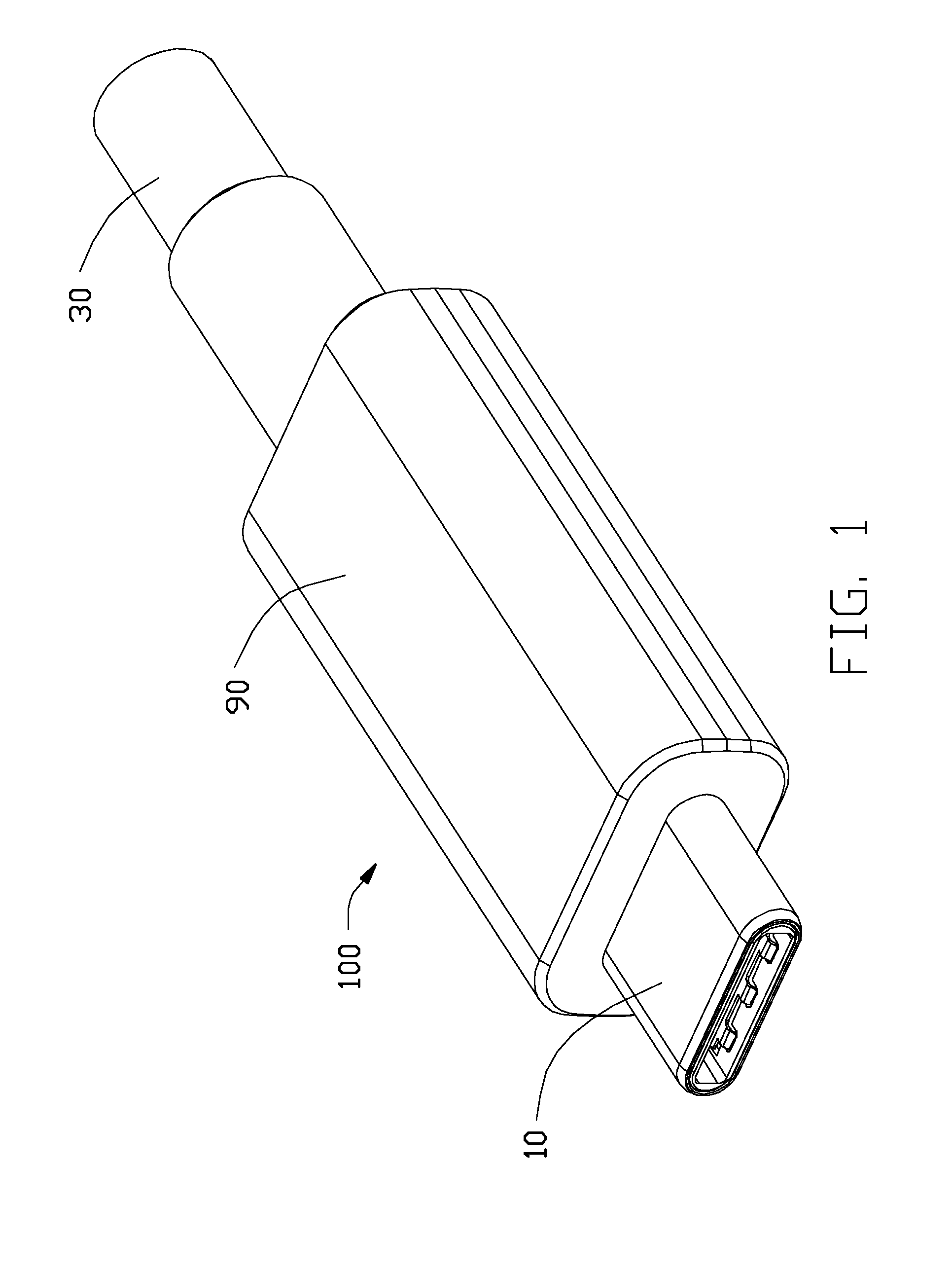
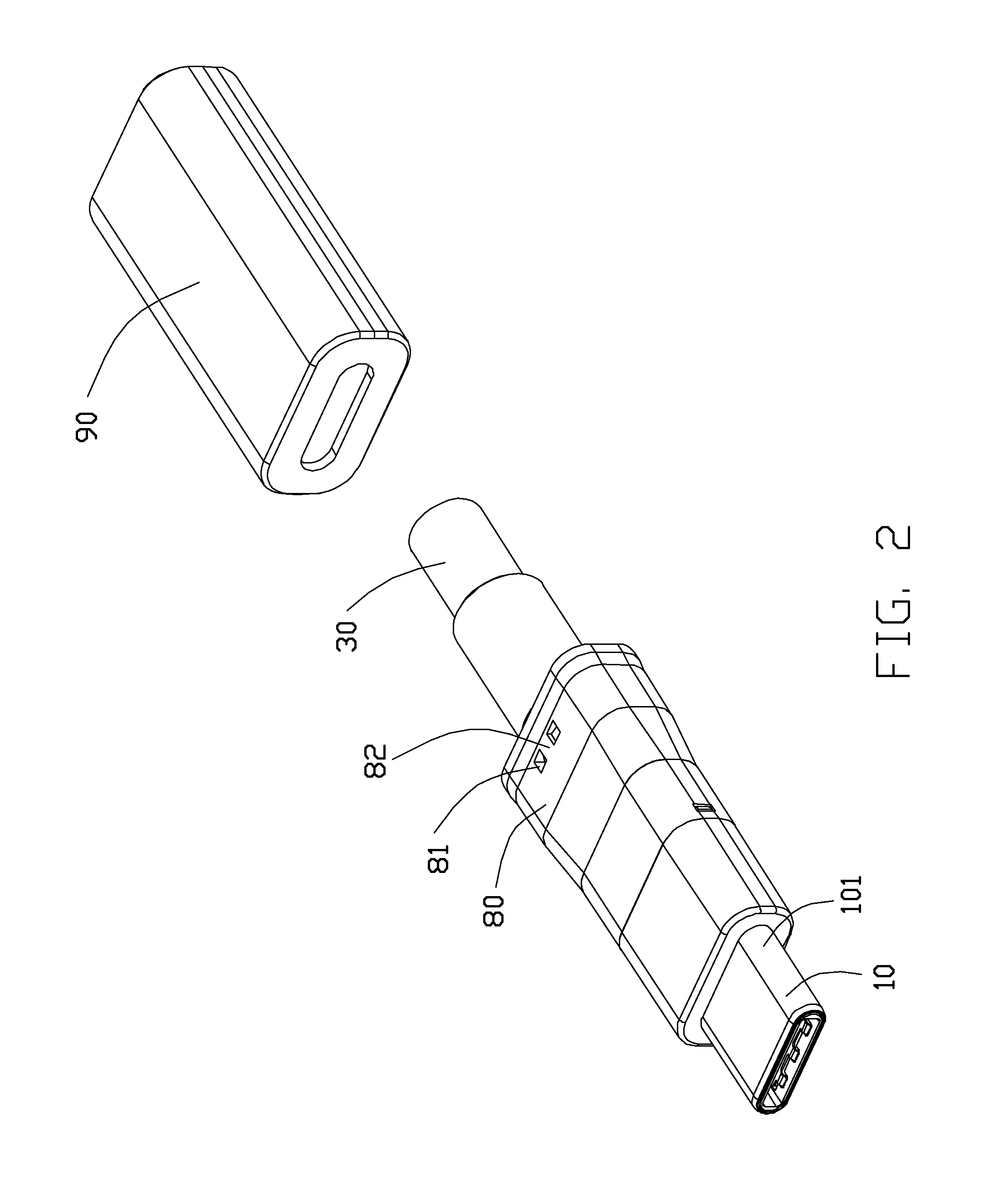
[0020]Referring to FIGS. 1-5, a cable connector assembly, e.g., a plug connector assembly 100, formed in accordance with the present invention for mating with a mating connector (not shown), comprises a mating member 10, an internal printed circuit board (PCB) 20 disposed behind and electrically connecting with the mating member 10, a cable 30 including a plurality of wires, namely a first type of wires 31 and a second type of wires 32, electrically connected with the PCB 20, a spacer 4 for positioning the wires 31 and 32, a shell including a second shell 50 having a closed circumference and a third shell 60 also having a closed circumference, a strain relief 80, an inner over-mold on the second shell 50, and an outer mold or over-mold 90. The plug connector assembly 100 can be mated with the mating connector in two orientations.

[0021]Referring to FIGS. 7 and 8, the mating member 1 compri...


PUM


Abstract

A method of manufacturing a cable connector assembly including the steps of: connecting a mating member to a cable through an internal printed circuit board; enclosing a shell over the mating member and the cable; fixing a number of dowel pins to the shell; molding a strain relief over the shell; removing the dowel pins to form a number of pinholes in the strain relief; and telescoping an outer over-mold on the strain relief along a front-to-back direction.

Description

BACKGROUND OF THE INVENTION[0001]1. Field of the Invention[0002]The present invention relates to a method of manufacturing a cable connector assembly, especially to forming a strain relief thereof.[0003]2. Description of Related Art[0004]US 2012 / 0071022, published on Mar. 22, 2012, discloses a cable connector assembly. The cable connector assembly includes a mating member connected through an internal printed circuit board to a cable, a shielding shell enclosing the mating member, a strain relief over-molded upon the shielding shell, and an outer boot telescoped on the strain relief. A first part of the strain relief encloses a ring portion of the shielding shell and a second part of the strain relief encloses the cable. During forming the strain relief, the shielding shell and the cable may drift due to high pressure. The strain relief may become uneven, certain part thereof being thick while another part thereof being thin. This unevenness will affect adhesion of the outer boot to...

Claims


Application Information

Patent Timeline
Patent Type & Authority Applications(United States)
IPC IPC(8): H01R13/58H01R43/16H01R43/20
CPCH01R13/5845H01R43/205H01R43/16H01R13/6585H01R24/60H01R2107/00
Inventor WU, JERRYCHEN, JUNMENG, FAN-BO
Owner FOXCONN INTERCONNECT TECH LTD
Why Eureka
Try Eureka