Methods and systems to harvest energy from the earth

Inactive Publication Date: 2012-09-20
SMITH DAVID RANDOLPH
View PDF9 Cites 3 Cited by
  • Summary
  • Abstract
  • Description
  • Claims
  • Application Information

AI Technical Summary

Benefits of technology

[0011]In one embodiment, the method further comprises the step of enhancing the temperature difference between the heat intake region and the heat exhaust region. In one embodiment, the enhancing step comprises: providing additional heating of the working fluid at the heat intake region, wherein the additional heating is powered by a renewable energy source. Alternatively, the enhancing step comprises: providing additional cooling of the working fluid at the heat exhaust region, wherein the additional cooling is powered by a renewable energy source. In one embodiment, the renewable energy source is selected from the group consisting of wind, solar, geothermal, and any combination thereof. In another embodiment, the working fluid is selected from the group consisting of helium, hydrogen, nitrogen, air, and any combination thereof.
[0012]According to another aspect of the present disclosure, there is provided an engine extracting geothermal energy comprisin

Problems solved by technology

These conventional methods of generating electricity have deleterious effects.
For instance, burning of coal and hydrocarbon release toxic and greenhouse gases into the environment.
In addition, mining and collection of the coal and hydrocarbon greatly damage the environment, as well as require other natural resources, such as water, in the operation.
Nuclear energy produces nuclear wastes, which can be significantly dangerous if released due to human error or natural disasters.
Further, due to the potential harm caused by the nuclear wastes, nuclear plants are often located in an isolated area, which can pose a challenge for distribution of the electricity.
However, current methods of harvesting geothermal energy also have disadvantages.
This often leaches significant amounts of minerals and other toxic substances from the subterranean environment during the energy collection operations.

Method used


Image

  • Methods and systems to harvest energy from the earth
  • Methods and systems to harvest energy from the earth
  • Methods and systems to harvest energy from the earth

Examples


Embodiment Construction

[0025]As used herein, “a” or “an” means one or more. Unless otherwise indicated, the singular contains the plural and the plural contains the singular. As described herein, the term “surface” can be the surface of the earth or surface of a body of water and includes locations at or above the surface of earth. The term “subterranean” includes locations below the surface of the earth. As used herein, geothermal energy encompasses any energy located below the surface of the earth. Also the term “heat engine” or “engine” encompasses any form of device that transforms heat energy into thermodynamic work.

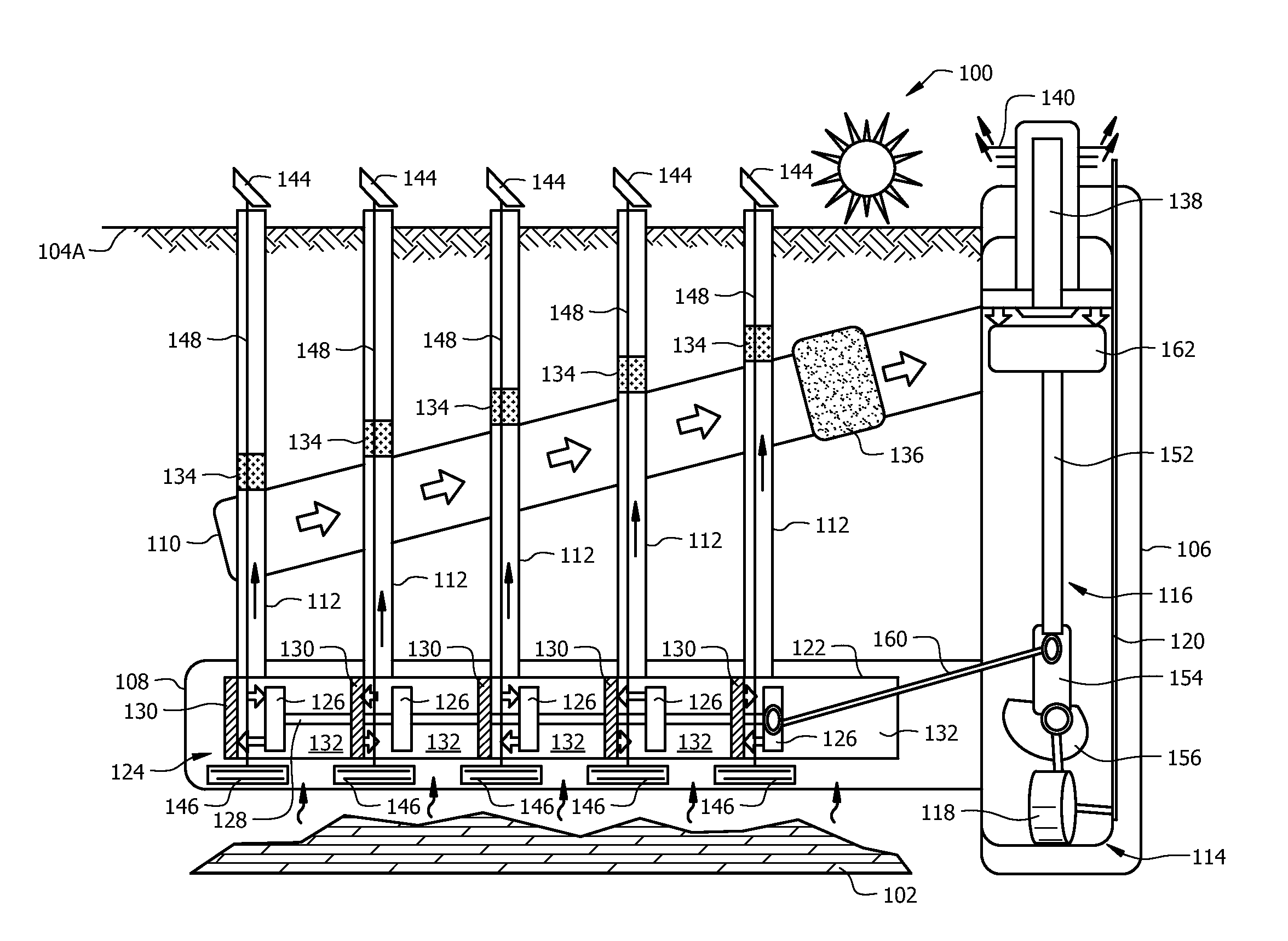
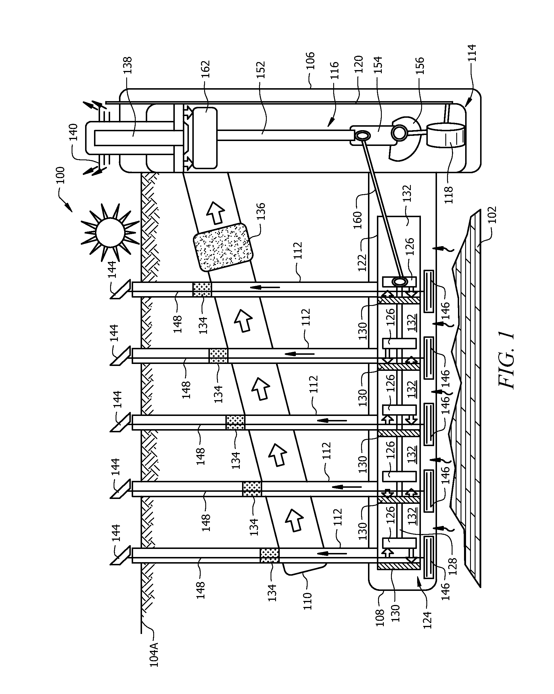
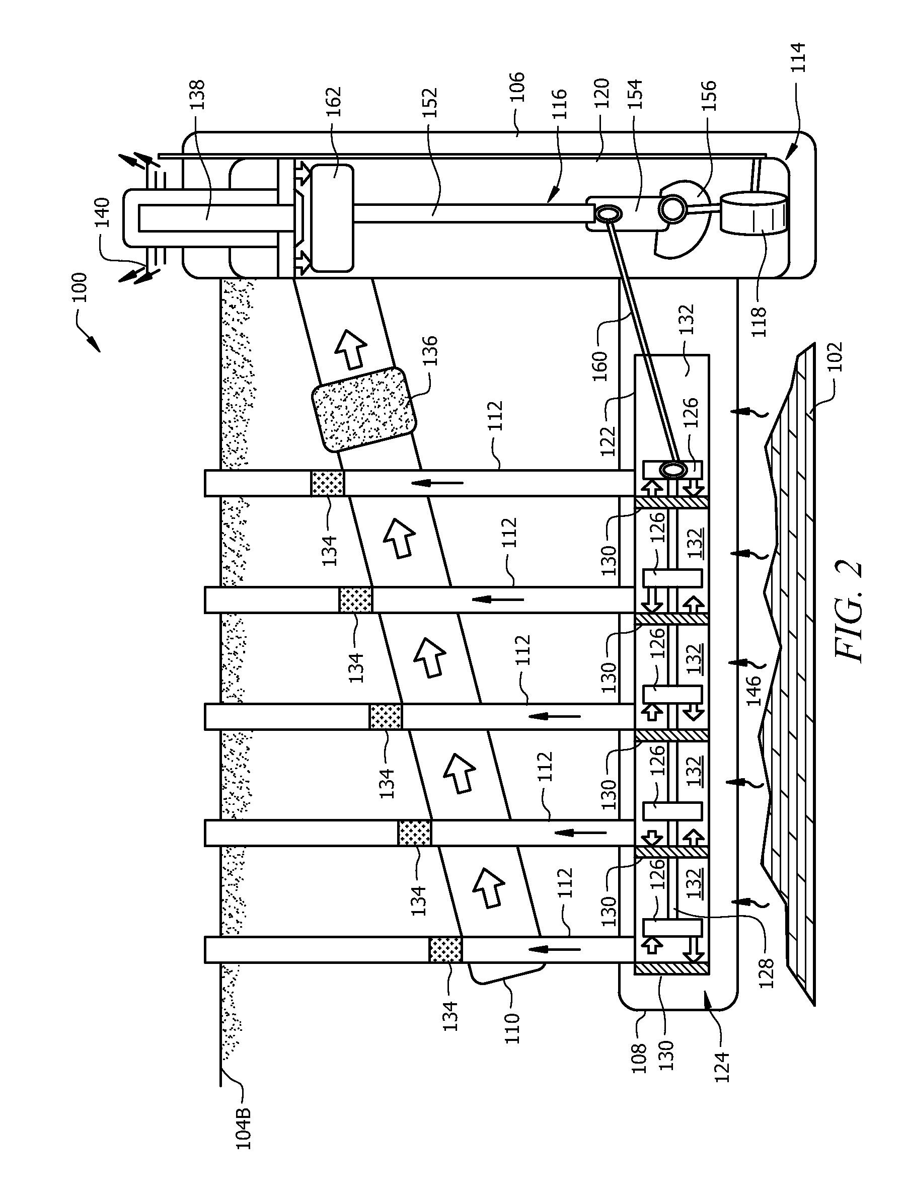
[0026]The present disclosure provides an engine assembly that is installed below the surface of the earth to harvest the geothermal energy of the earth by using a working fluid in a closed loop system, and convert it into electricity. The subterranean engine comprises a hot region or a heat intake region, a cold region or a heat exhaust region, and a working fluid that moves between the t...


PUM


Abstract

The present disclosure provides an engine assembly that is installed below the surface of the earth to harvest the thermal energy of the earth, using a working fluid in a closed loop system, and convert it into electricity, which can be commercialized at the surface. The subterranean engine comprises a hot region and a cold region, and a working fluid that moves between the two regions. The movement and efficiency of the working fluid operates the pistons that drive a generator coupled to the pistons, thereby generating electricity. The hot region of the engine is primarily powered by the geothermal energy. The engine can further incorporate renewable energy to improve the movement of the working fluid between the hot and cold regions. The system can further be used to store renewable energy below ground.

Description

CROSS REFERENCE[0001]The present application claims the benefit of U.S. Provisional Patent Application No. 61 / 453699, filed Mar. 17, 2011 and entitled “METHOD AND APPARATUS TO SUBDUE ENERGY FROM THE EARTH,” the disclosure of which is incorporated by reference herein in its entirety.TECHNICAL FIELD[0002]The present disclosure is directed to methods and apparatus to harvest thermal energy from the earth, and more particularly to using one or more well bores to collect energy from the subterranean environment of the earth and convert it into electrical power.BACKGROUND[0003]Technological advancements in all fields, such as agriculture, manufacturing transportion, communication, require energy. To date, mankind has relied heavily on coal, hydrocarbon, and nuclear materials to generate energy and power for these advancements.[0004]These conventional methods of generating electricity have deleterious effects. For instance, burning of coal and hydrocarbon release toxic and greenhouse gases...

Claims


Application Information

Patent Timeline
IPC IPC(8): F03G7/04
CPCF03G7/04F02G1/043Y02E10/10
Inventor SMITH, DAVID R.
Owner SMITH DAVID RANDOLPH
Why Eureka
Try Eureka