Temperature control method of refrigerator

A temperature control method and refrigerator technology, which are applied to household refrigerators, refrigerators, refrigeration components, etc., can solve the problems of limited improvement in temperature difference, temperature difference in refrigerating room, weak air-conditioning convection, etc., so as to improve electric power and prevent space from being overcooled. , Improve the effect of temperature difference

Inactive Publication Date: 2004-10-06
LG ELECTRONICS INC
View PDF0 Cites 19 Cited by
  • Summary
  • Abstract
  • Description
  • Claims
  • Application Information

AI Technical Summary

Problems solved by technology

[0043] However, in the temperature control method of the above-mentioned prior art refrigerator, there is a problem that since the cold air discharged into the above-mentioned refrigerating room R has a limit to uniform convection in the inside of the above-mentioned refrigerating room R, the convection of the cold air will be relatively opposite. Weaker weakly cold parts, as a result of which a temperature difference is generated in the above-mentioned refrigerating room R
[0044] Therefore, in order to discharge the cold air to the weakly cold part, a second cold air discharge duct is further formed inside the partition wall 2, and a nozzle is provided on the second cold air discharge duct, thereby eliminating the temperature difference in the refrigerating room R. , but in the case of opening and closing the above-mentioned nozzle at the same time as the above-mentioned damper 24, the degree of improvement of the temperature difference is limited

Method used


Image

  • Temperature control method of refrigerator
  • Temperature control method of refrigerator
  • Temperature control method of refrigerator

Examples


Embodiment Construction

[0060] Preferred embodiments of the present invention will be described in detail below with reference to the accompanying drawings.

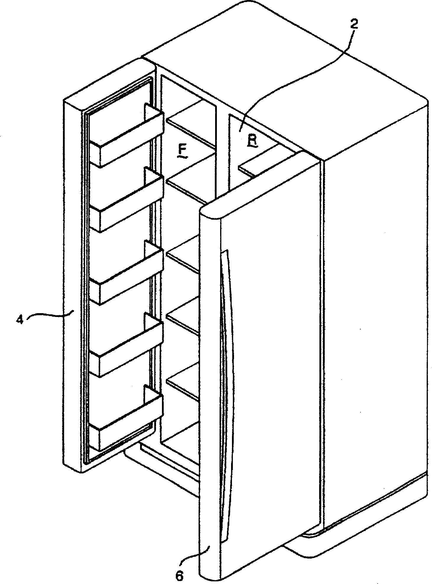
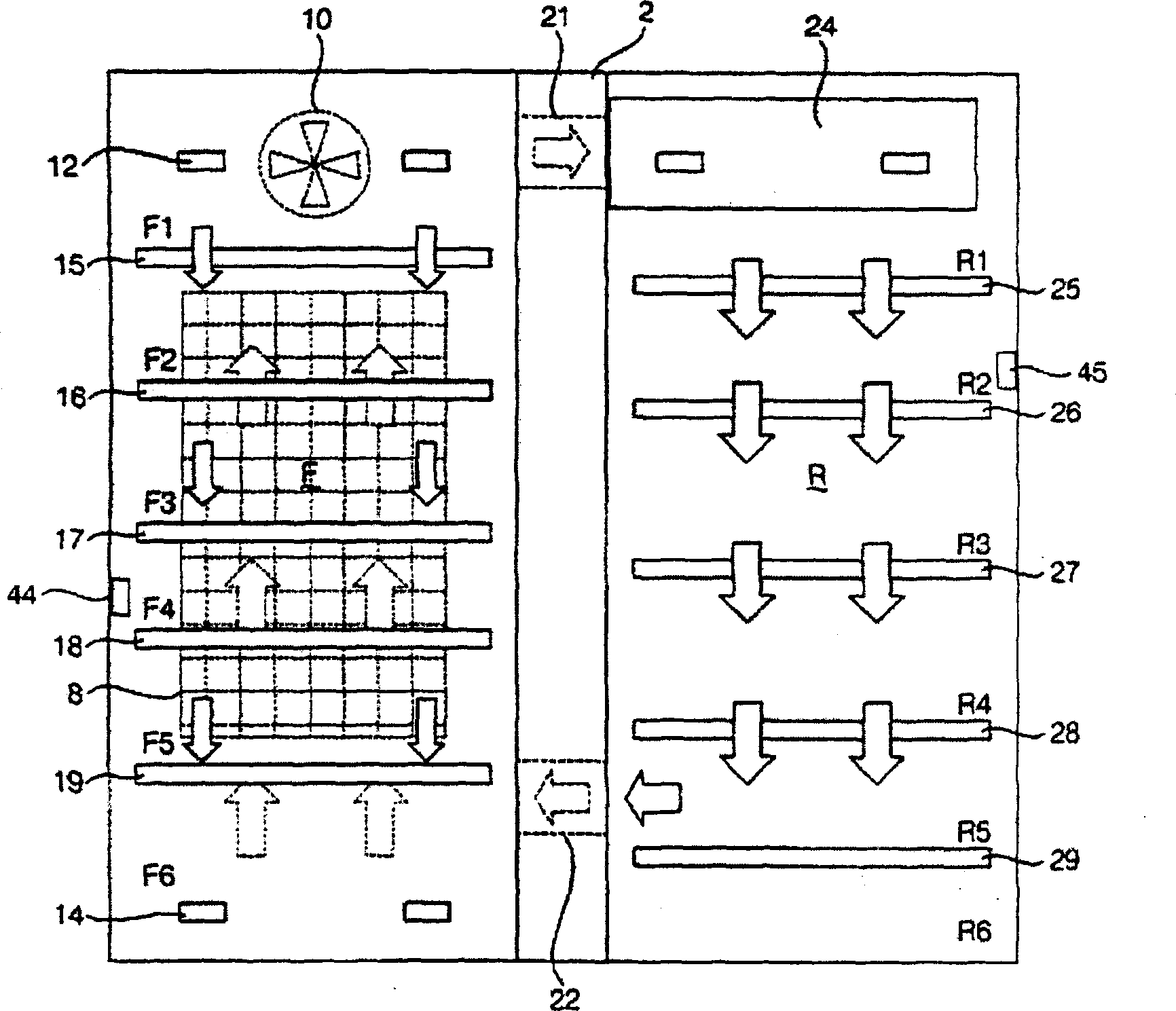
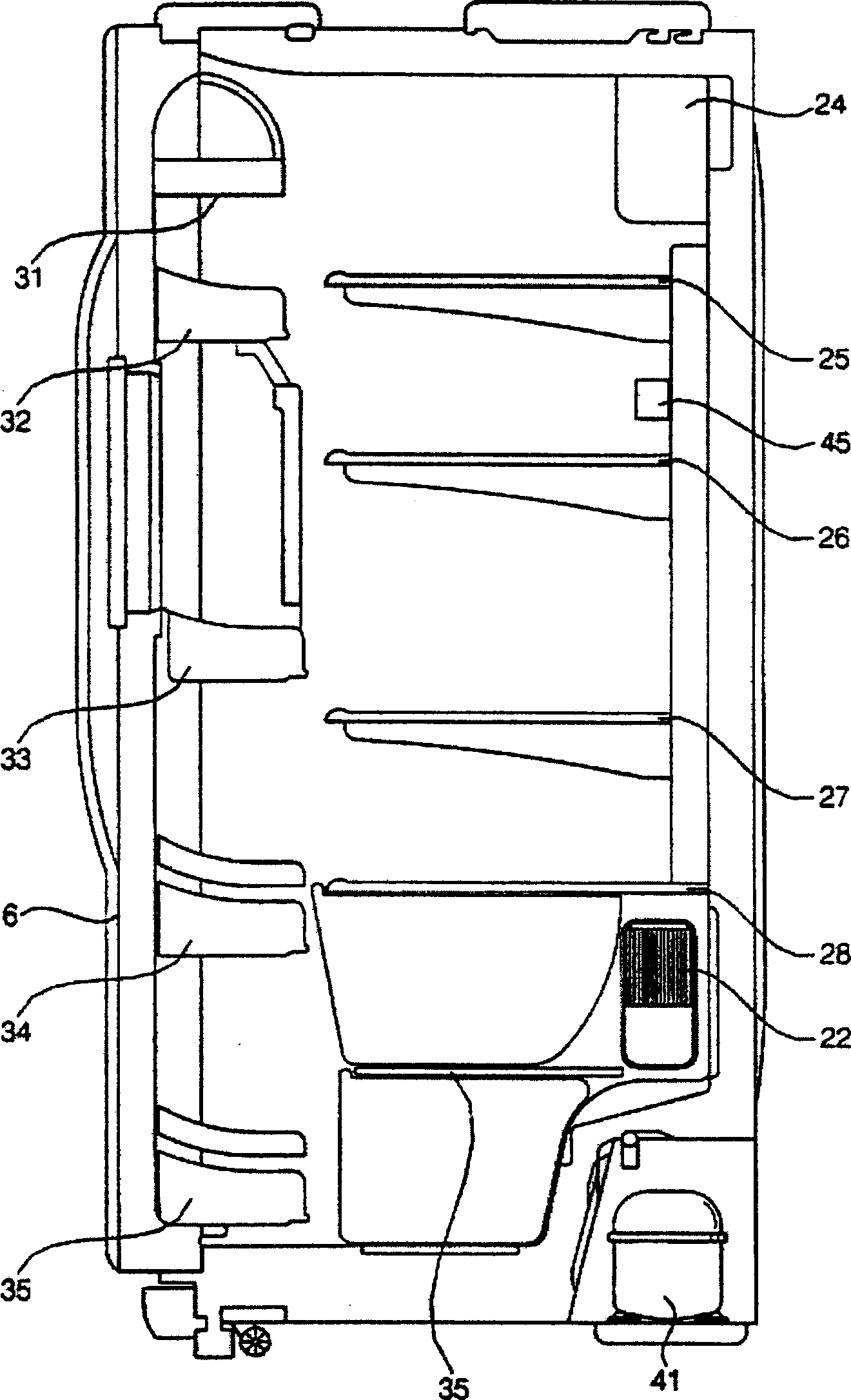
[0061] Figure 6 is a front view showing an internal structure of a refrigerator according to an embodiment of the present invention, Figure 7 It is a side view showing the inner structure of the refrigerator compartment of the refrigerator according to one embodiment of the present invention.

[0062] The refrigerator of one embodiment of the present invention is as Figure 6 and Figure 7 As shown, a second cold air discharge pipe 52 is formed on the partition 2, one end of the second cold air discharge pipe 52 communicates with the cold air discharge pipe 21, and the other end communicates with a part of the spaces R2-R4 of the plurality of refrigerated spaces R1-R6, In addition, nozzles 62 to 64 for spraying the cold air passing through the second cold air discharge duct 52 to some of the spaces R2 to R4 in the plurality of refrigerated...


PUM


Abstract

Disclosed is a temperature control method for a refrigerator which can minimize a deviation in refrigerant compartment temperature while minimizing the power consumption of the refrigerator. The temperature control method includes the steps of (A) comparing a sensed temperature of a freezing compartment with a predetermined maximum freezing compartment temperature and a predetermined minimum freezing compartment temperature, respectively, thereby controlling a compressor and a circulating fan to be turned on or off such that the sensed freezing compartment temperature is ranged between the predetermined maximum and minimum freezing temperatures, (B) comparing, following the step (A), a sensed temperature of a refrigerating compartment defined with a plurality of refrigerating chambers therein, with a predetermined maximum refrigerating compartment temperature and a predetermined minimum refrigerating compartment temperature, respectively, thereby controlling a damper to be opened or closed and the circulating fan to be turned on or off such that the sensed refrigerating compartment temperature is ranged between the predetermined maximum and minimum refrigerating temperatures, and (C) discharging cold air into at least one of the refrigerating chambers when the damper is closed, and the compressor and the circulating fan are turned on.

Description

technical field [0001] The present invention relates to a temperature control method of a refrigerator, in particular to a method that does not additionally drive a compressor and a circulation fan, but provides cold air to the weakly cold part of the refrigerator, so as to minimize the temperature difference of the refrigerator and minimize power consumption The temperature control method of the refrigerator. Background technique [0002] Generally, a so-called refrigerator refers to a device that uses a refrigeration cycle device composed of a compressor, a condenser, an expander, and an evaporator to maintain a low temperature in a freezer compartment and a refrigerator compartment. [0003] figure 1 A perspective view showing a state in which a freezer compartment and a refrigerator compartment are opened in a related art refrigerator. [0004] Refrigerators in the prior art such as figure 1 As shown, the freezer compartment is partitioned left and right by a partitio...

Claims


Application Information

Patent Timeline
Patent Type & Authority Applications(China)
IPC IPC(8): F25D17/06F25D11/02F25D17/04F25D17/08F25D29/00
CPCF25D17/045F25D29/00F25D17/065F25B2600/112F25D2700/122F25D2400/06
Inventor 南泳硕赵晟浩郑润澈崔济虎
Owner LG ELECTRONICS INC
Why Eureka
Try Eureka