Multi-Faceted Designs for a Direct Exchange Geothermal Heating/Cooling System

a geothermal heating/cooling system and geothermal direct exchange technology, applied in the direction of refrigeration machines, compressors with reversible cycles, refrigeration safety arrangements, etc., can solve the problems of compressor damage, dx system with vertically oriented geothermal heat exchange tubing, and dx system with dx system operation efficiency levels that are not acceptable, so as to achieve the highest possible operational efficiency, reduce overall system operation efficiency levels, and enhance heat transfer

Active Publication Date: 2008-07-24
WIGGS B RYLAND
View PDF99 Cites 21 Cited by
  • Summary
  • Abstract
  • Description
  • Claims
  • Application Information

AI Technical Summary

Benefits of technology

[0049]Such a heat exchanger would consist of, for example, the warm liquid line (preferably finned at this particular pre-heater location) being disposed within an insulated containment vessel, such as a tube, or the like, transferring the warmer heat within the liquid refrigerant exiting the air handler (before the heating mode expansion device) to the cooler vapor exiting from the ground on its way to the system's compressor, so as to effect natural heat exchange via heat naturally flowing to cold. The containment vessel would preferably be liquid filled so as to enhance heat transfer between the respective liquid line and vapor line segments within the containment vessel. The respective liquid and vapor transport lines could also be directly wrapped around one another and insulated as another means of providing the subject heat transfer, for example.
[0050]While it is known to use the heat in the refrigerant exiting the interior air handler in a low temperature air-source heat pump system, the use of such heat is made via a secondary system compressor, which requires an additional system power draw. An additional secondary compressor provides warmer interior air but also decreases overall system operational efficiency levels, which is counterproductive in a DX system application where the highest possible operational efficiencies are usually a primary concern.

Problems solved by technology

When a sufficient quantity of oil accumulates in the bottom of the cylinder, a steel float, or the like, rises to expose a hole through which the oil is pulled, via compressor suction, back directly into the compressor itself via an oil return line from the bottom of the oil separator to the compressor, Conventional separators, however, typically only filter to 100 microns and are only 80% to 90% efficient, which is unacceptable for a DX system with vertically oriented geothermal heat exchange tubing.
Testing has shown that, in a DX system, it most of the lubricating oil within the compressor is not kept out of the geothermal heat exchange field lines, especially if the field lines are vertically inclined, the oil from the compressor will tend to remain in the field lines when the DX system is operating in the heating mode, and the compressor will be damaged from lack of adequate return lubrication.

Method used


Image

  • Multi-Faceted Designs for a Direct Exchange Geothermal Heating/Cooling System
  • Multi-Faceted Designs for a Direct Exchange Geothermal Heating/Cooling System
  • Multi-Faceted Designs for a Direct Exchange Geothermal Heating/Cooling System

Examples


Embodiment Construction

[0057]The following detailed description is of the best presently contemplated mode of carrying out the claimed subject matter. The description is not intended in a limiting sense, and is made solely for the purpose of illustrating the general principles of the disclosure. The various features and advantages of this disclosure may be more readily understood with reference to the following detailed description taken in conjunction with the accompanying drawings.

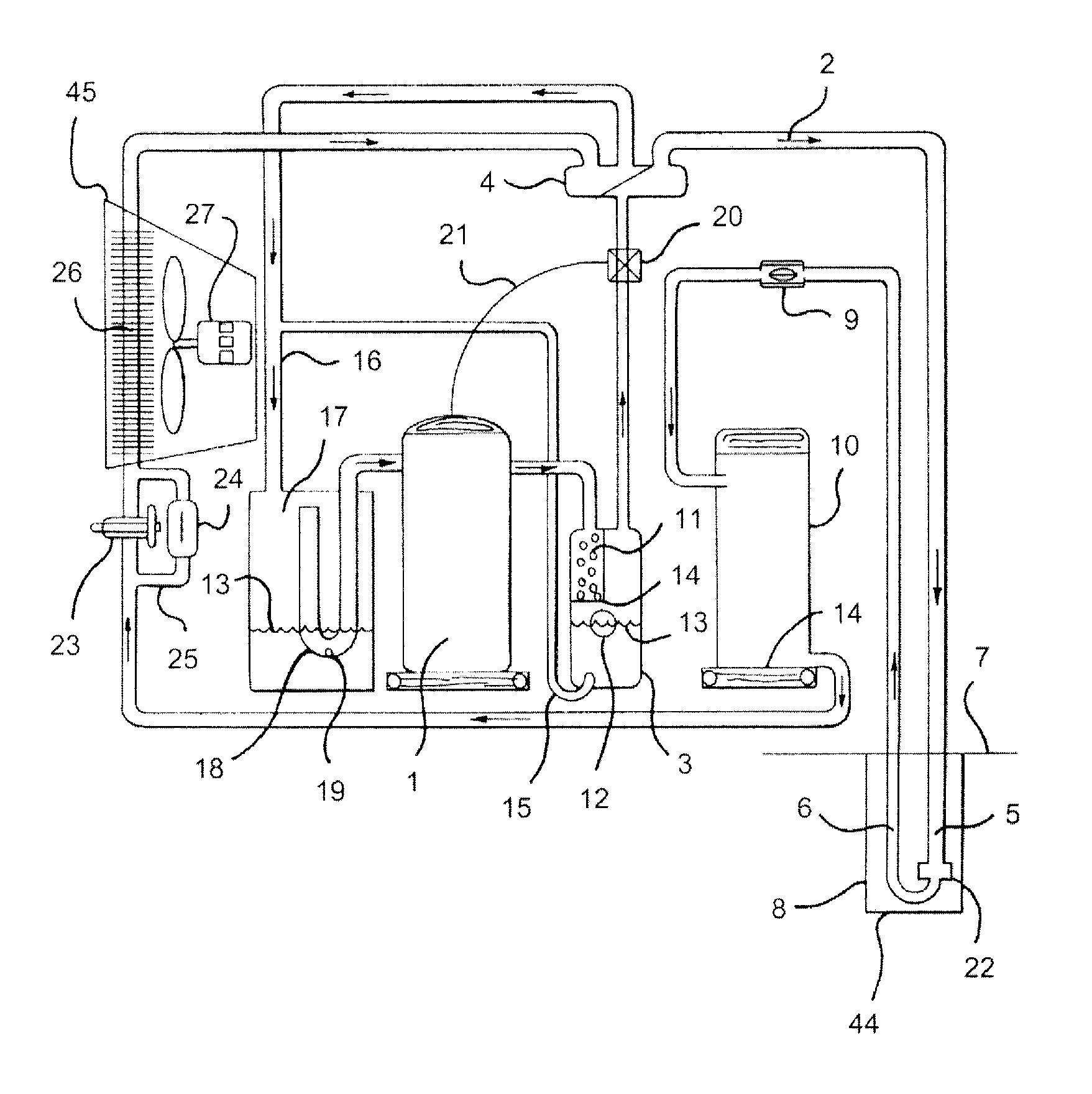
[0058]Referring now to the drawings in detail, where like numerals refer to like parts or elements, FIG. 1 shows a side view, not drawn to scale, of a DX heat pump system operating in the cooling mode. The system includes a compressor 1, with a hot gas vapor refrigerant (not shown except for arrows 2 indicating the direction of the refrigerant flow) traveling from the compressor 1 into an oil separator 3. The compressor 1 is designed with an operating BTU capacity of between 80% and 95% of the maximum calculated heating / coolin...


PUM


Abstract

A direct exchange heating/cooling system with at least one of a reduced compressor size, with a 500 psi high pressure cut-off switch, with a 98% efficient oil separator, with extra oil, operating at a higher pressure than an R-22 system, with receiver design parameters for efficiency and fox capacity, with geothermal heat exchange line set design parameters, with special heating/cooling expansion device sizing and design, with a specially sized air handler, and with a vapor line pre-heater.

Description

CROSS-REFERENCE TO RELATED APPLICATIONS[0001]This application claims the benefit of U.S. Provisional Application No. 60 / 881,000, filed Jan. 18, 2007.FIELD OF THE DISCLOSURE[0002]The present disclosure relates to a geothermal direct exchange (“DX”) heating / cooling system, which is also commonly referred to as a “direct expansion” heating / cooling system, comprising various design improvements.BACKGROUND OF THE DISCLOSURE[0003]Conventional geothermal ground source / water source heat exchange systems typically use liquid-filled closed loops of tubing (typically approximately ¼ inch wall polyethylene tubing) buried in the ground, or submerged in a body of water, so as to either absorb heat from, or to reject heat into, the naturally occurring geothermal mass and / or water surrounding the buried or submerged liquid transport tubing. The tubing loop, which is typically filled with water and optional antifreeze and rust inhibitors, extends to the surface. A water pump circulates the naturally...

Claims


Application Information

Patent Timeline
Patent Type & Authority Applications(United States)
IPC IPC(8): F24J3/08
CPCF25B13/00F25B30/06F25B49/005F25B2600/0271F25B2400/12F25B2500/01F25B2313/002F25B49/00
Inventor WIGGS, B. RYLAND
Owner WIGGS B RYLAND
Why Eureka
Try Eureka