Module for cooling semiconductor device

a semiconductor device and module technology, applied in the field of modules for cooling semiconductor devices, can solve the problems of large amount of heat generated, insufficient heat absorption of peltier devices (tec), and insufficient heat absorption of heat pipes. achieve the effect of improving cooling efficiency

a semiconductor device and module technology, applied in the field of modules for cooling semiconductor devices, can solve the problems of large amount of heat generated, insufficient heat absorption of peltier devices (tec), and insufficient heat absorption of heat pipes. achieve the effect of improving cooling efficiency

US20100269517A1Inactive Publication Date: 2010-10-28FURUKAWA ELECTRIC CO LTD

Image

  • Module for cooling semiconductor device
  • Module for cooling semiconductor device
  • Module for cooling semiconductor device

Examples


example 1

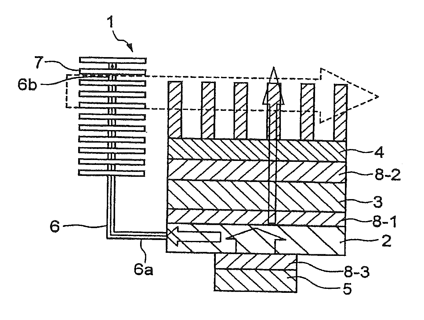
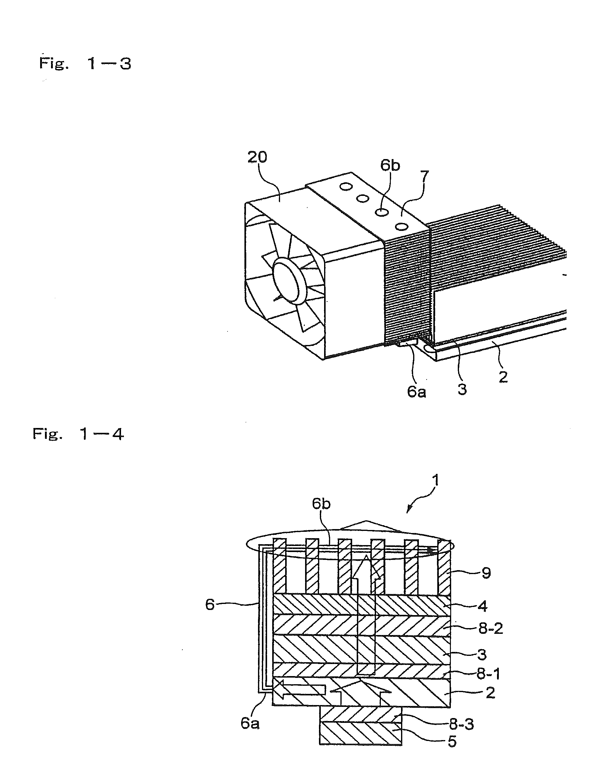
[0126]The module for cooling a heat generating element of the invention as shown in FIG. 2-2 is prepared. More specifically, a heat receiving plate formed by a material having a high thermal conductivity such as aluminum or copper is attached to a heat generating source such as a CPU mounted on a printed board. At least one prescribed recessed portion (for example, a hole) is formed in the heat receiving plate, and an end of a heat transfer device having a low thermal resistance such as a heat pipe is thermally connected to the recessed portion and fixed therein.

[0127]The other end of the heat pipe (heat transfer device) is thermally connected to a prescribed recessed portion (for example, a hole having a prescribed diameter) formed in a heat dissipating plate formed by a material having a high thermal conductivity such as aluminum or copper. The heat pipe is fixed to the above recessed portion of the hear receiving plate and the heat dissipating plate by soldering, crimping or the ...

example 2

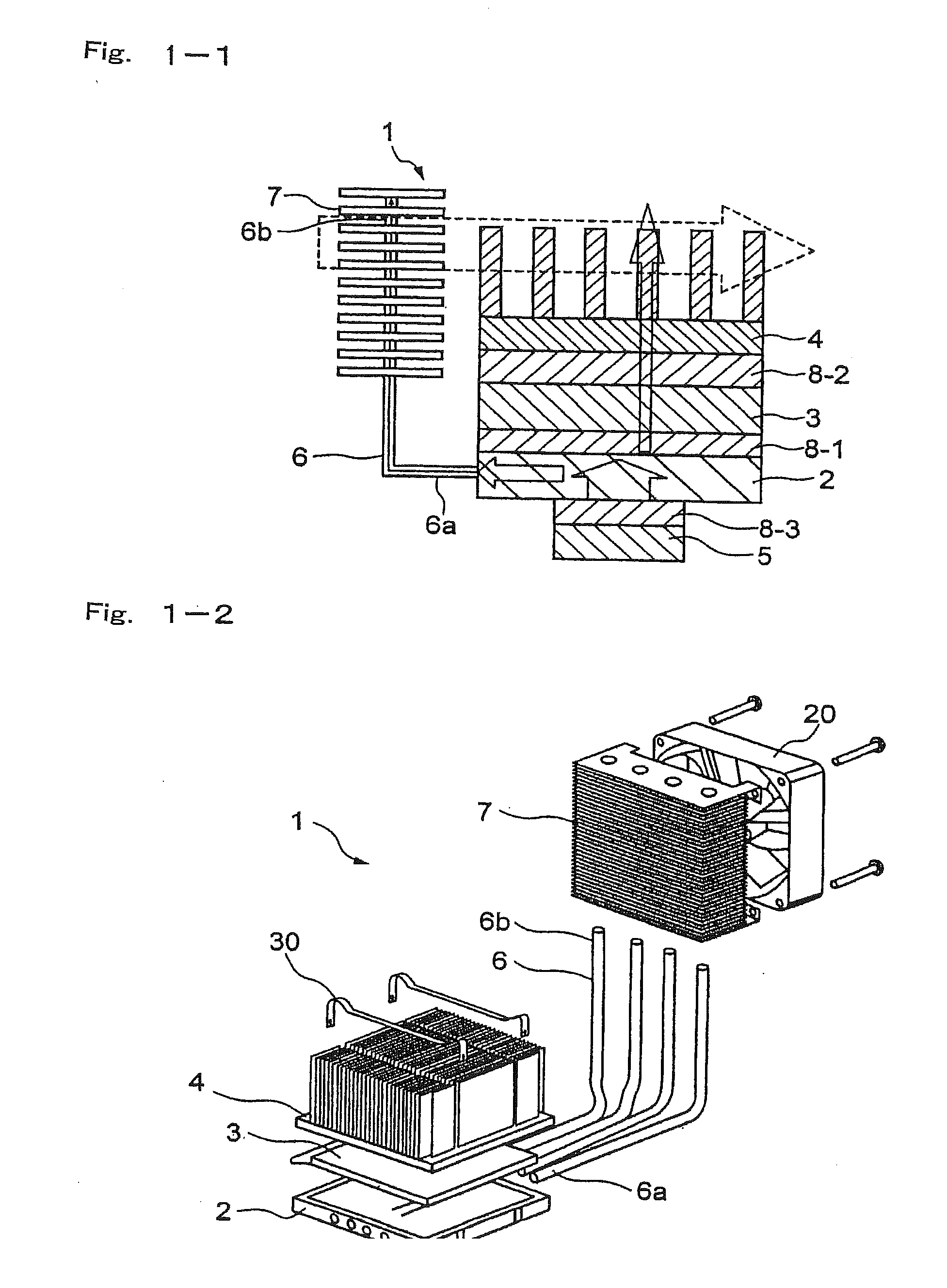
[0141]The module for cooling a heat generating element of the invention as shown in FIG. 2-4 is prepared. The module is substantially the same as the module for cooling a heat generating element as shown in FIG. 2-2 except that the heat receiving plate is arranged so as to be parallel to the heat dissipating plate. In FIG. 2-4, the first heat sink is placed at the lower side of the heat dissipating plate, however, the first heat sink may be placed at the upper side of the heat dissipating plate and the second heat sink may be place at the lower side of the heat dissipating plate.

[0142]In addition, the module for cooling a heat generating element of the invention as shown in FIG. 2-5 is prepared. More specifically, the heat receiving plate is arranged so as to be parallel to the heat dissipating plate, and furthermore, the third heat sink is attached to the heat receiving plate in addition to the first heat sink and the second heat sink as described with reference to FIG. 2-4. The th...


PUM


Abstract

A module for cooling a heat generating element comprising a heat receiving plate thermally connected to at least one heat generating element; a heat transfer device one end portion of which is thermally connected to the heat receiving plate and other end portion of which is thermally connected to a heat dissipating plate; a thermoelectric cooler one face of which is thermally connected to one face of the heat dissipating plate; a first heat sink thermally connected to other face of the heat dissipating plate; and a second heat sink thermally connected to other face of said thermoelectric cooler.

Description

CROSS REFERENCE TO RELATED APPLICATIONS[0001]The present application is a continuation application of U.S. patent application Ser. No. 10 / 985,412, filed on 11 Nov. 2004, the entire contents of which are incorporated herein by reference. The Ser. No. 10 / 985,412 application claimed the benefit of the date of the earlier filed Provisional Application No. 60 / 552,149 filed 11 Mar. 2004. Priority under 35 U.S.C. ยง 119(a) is also hereby claimed from Japanese Application No. 2004-221766, filed 29 July 2004, the disclosure of which is also incorporated herein by reference.FIELD OF THE INVENTION[0002]The present invention relates to a cooling device for cooling an element to be cooled having a high heat generating density such as semiconductor elements using a thermoelectric cooler (which is also referred to as TEC), for example a Peltier cooler.BACKGROUND OF THE INVENTION[0003]Recently, an electronic appliance includes high power and densely integrated components such as microprocessor there...

Claims


Application Information

Patent Timeline
28 Oct 2010
Publication
US20100269517A1
IPC
F25B21/02; F25D23/12
CPC
F25B21/02; F25B2321/0212; F28F1/32; F25B2321/0252; F28D15/0266; F25B2321/0251
Inventors
IKEDA, MASAMI; KIMURA, YUICHI