Multistage-cascaded compression type heat pump set under large temperature difference

A compression heat pump, large temperature difference technology, applied in compressors, compressors with multiple evaporators, compressors with multiple condensers, etc., can solve the problem of reduced system performance coefficient and reduced energy utilization efficiency , evaporating pressure reduction and other problems, to achieve the effect of improving the comprehensive energy utilization efficiency and economy of the system, increasing the cooling capacity and system energy efficiency, and reducing the irreversible heat transfer loss

Inactive Publication Date: 2007-12-26
TSINGHUA UNIV
View PDF0 Cites 22 Cited by
  • Summary
  • Abstract
  • Description
  • Claims
  • Application Information

AI Technical Summary

Problems solved by technology

When the inlet water temperature is constant, a large temperature difference and a small flow rate mean that the temperature of the hot water supply increases and the temperature of the cold water outlet decreases. For common heat pump devices, it will cause an increase in the condensation pressure and a decrease in the evaporation pressure, resulting in system failure. Lower coefficient of performance (COP) and lower energy efficiency

Method used


Image

  • Multistage-cascaded compression type heat pump set under large temperature difference
  • Multistage-cascaded compression type heat pump set under large temperature difference

Examples


Embodiment 1

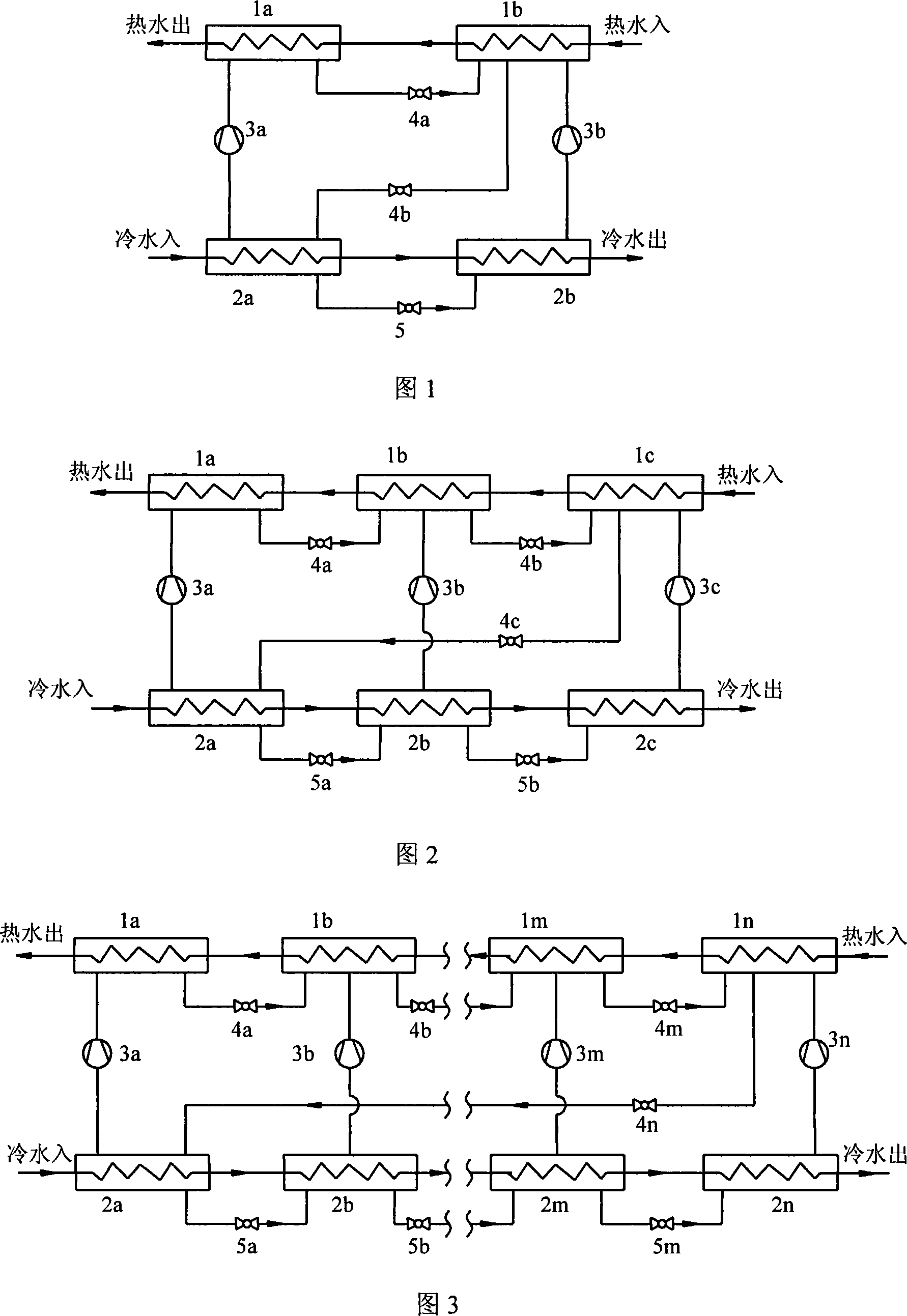
[0016] Example 1: Two-stage series connection of large temperature difference compression heat pump unit

[0017] As shown in Figure 1, the heat pump unit has a first-stage evaporator 2a, a first-stage compressor 3a, a first-stage condenser 1a, a first-stage condenser outlet refrigerant throttling device 4a, and a first-stage evaporator outlet The refrigerant throttling device 5a is composed of the second-stage evaporator 2b, the second-stage compressor 3b, the second-stage condenser 1b, and the second-stage condenser outlet refrigerant throttling device 4b. The pressure of the first-stage condenser 1a is greater than the pressure of the second-stage condenser 1b, the pressure of the second-stage condenser 1b is greater than the pressure of the first-stage evaporator 2a, and the pressure of the first-stage evaporator 2a is greater than the pressure of the second-stage evaporator 2b. The superheated or saturated refrigerant vapor from the first-stage evaporator 2a is compressed...

Embodiment 2

[0018] Example 2: Three-stage series series large temperature difference compression heat pump unit

[0019]As shown in Figure 2, the heat pump unit has a first-stage evaporator 2a, a first-stage compressor 3a, a first-stage condenser 1a, a first-stage condenser outlet refrigerant throttling device 4a, and a first-stage evaporator outlet Refrigerant throttling device 5a and second-stage evaporator 2b, second-stage compressor 3b, second-stage condenser 1b, second-stage condenser outlet refrigerant throttling device 4b, second-stage evaporator outlet refrigerant throttle The flow device 5b is composed of the third-stage evaporator 2c, the third-stage compressor 3c, the third-stage condenser 1c, and the third-stage condenser outlet refrigerant throttling device 4c. Among them, the pressure of the first-stage condenser 1a is greater than the pressure of the second-stage condenser 1b, the pressure of the second-stage condenser 1b is greater than the pressure of the third-stage evap...


PUM


Abstract

This invention relates to a multi-stage serial large temperature-difference compression thermal pump set composed of multiple stages of condensers, evaporators, a compressor and a related throttle device and connection pipelines, in which the waterway systems of the condensers of each stage and evaporators are serial to form a connected in-out system of waterway, pipelines of cold-producing medium of the adjacent condensers are serial by the throttle device, the condenser of the last stage is connected with the evaporator of the first stage by the compressor to form a channel of cold-producing medium.

Description

technical field [0001] The invention belongs to a heat pump unit for heating, cooling and hot water supply, in particular to a high-efficiency compression heat pump unit capable of obtaining a large inlet and outlet temperature difference on both the cold and heat source sides. Background technique [0002] At present, various heat pump devices have been widely used in various heating, cooling and hot water supply systems. Among them, in medium and large heating and air conditioning systems, water-water compression heat pumps have been widely used, such as using groundwater. , surface water or industrial waste hot water and other heat pump cold and hot water units as low-temperature heat sources. In order to reduce the energy consumption of transportation, save the amount of water, and reduce the initial investment of the transmission and distribution system, it is generally easy to operate with a large temperature difference and a small flow on the water side. Under the co...

Claims


Application Information

Patent Timeline
Patent Type & Authority Applications(China)
IPC IPC(8): F25B6/04F25B5/04
Inventor 付林张世钢肖常磊陈闯刘燕
Owner TSINGHUA UNIV
Why Eureka
Try Eureka