Structure of thermopile sensor

a technology of thermopile sensor and structure, which is applied in the direction of heat measurement, instruments, optical radiation measurement, etc., can solve the problems of increasing fabrication procedures and manufacturing difficulties, and achieve the effect of improving the structure of the thermopile sensor and enhancing the sensing performan

Inactive Publication Date: 2005-02-17
OPTO TECH
View PDF2 Cites 19 Cited by
  • Summary
  • Abstract
  • Description
  • Claims
  • Application Information

AI Technical Summary

Benefits of technology

[0009] The object of the invention is to provide an improved str

Problems solved by technology

In addition, the improved structure will not incre

Method used


Image

  • Structure of thermopile sensor
  • Structure of thermopile sensor
  • Structure of thermopile sensor

Examples


Embodiment Construction

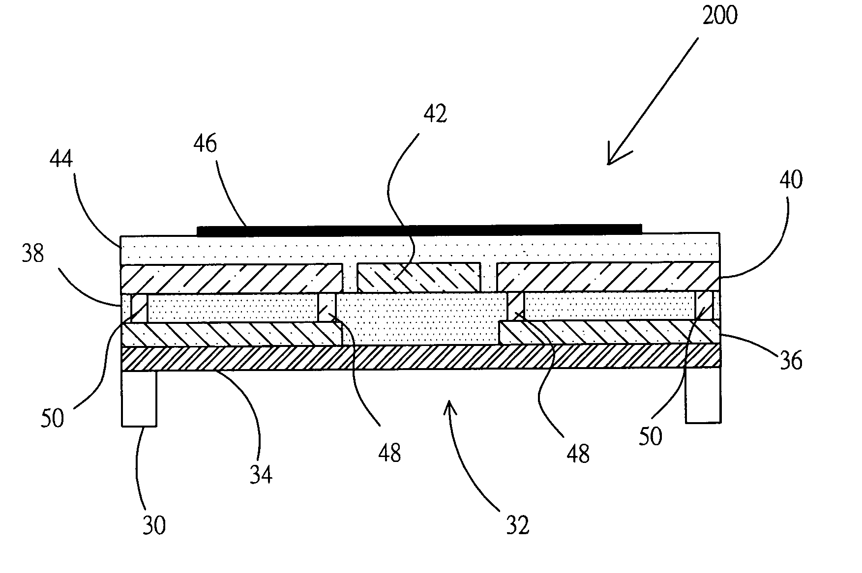
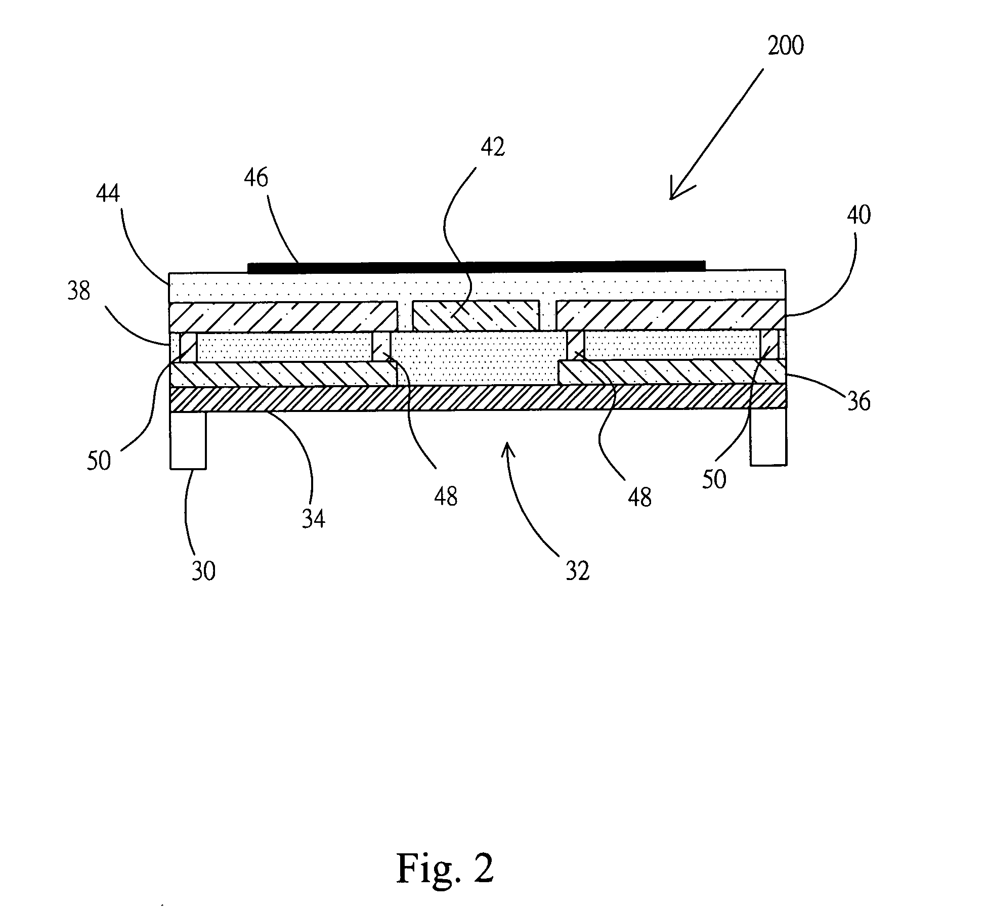
[0017] The invention is designed with a purpose in mind that the sensing performance should be enhanced without increasing the noise. Therefore, the invention improves the structure of a thermopile sensor on the basis of a conventional structure to achieve the above-mentioned purpose. The invention provides a heat-conducting structure at the center of a membrane to change the temperature distribution so that the temperature difference generated between the hot junctions and the cold junctions may become larger to enhance the sensing performance.

[0018]FIG. 2 is a schematic diagram showing an improved structure of the thermopile sensor 200 provided by the invention. The invention provides a single crystalline silicon substrate 30 and a cavity 32 that is a recess on the front side or backside of the substrate 30 formed by anisotropic etching. Besides, a membrane 34 covers the cavity 32, and the membrane 34 is composed of more than one layer of insulation film. Then, one or more than o...


PUM


Abstract

The invention relates to an improved structure of a thermopile sensor, which is to employ a membrane to cover a substrate that has a cavity. Besides, a plurality of thermoelectric elements is formed on the membrane extending outwards from the central side of the membrane and is composed of two different materials connected in series. The material of the element can be a composite of metal material and semiconductor material, and an insulation layer partitions the two materials; therefore, the two materials are connected in series through a contact hole. In addition, the contact hole formed at the central side of the membrane is called hot junction, whereas the contact hole formed at the side of the substrate is called cold junction. Moreover, to enhance the sensing performance of the thermopile sensor, a heat-conducting layer is formed at the center of the membrane, and after the heat-conducting layer is covered with another insulation layer, an absorption film is formed. The invention changes the temperature difference distribution by adding in a heat-conducting layer so as to enhance the sensing performance.

Description

BACKGROUND OF THE INVENTION [0001] 1. Field of the Invention [0002] The invention relates to an improved structure of a thermopile sensor that enhances the sensing performance. [0003] 2. Description of the Related Art [0004] A thermopile sensor device has been broadly applied to products such as ear thermometers, fire alarm devices, and smart house appliances for various functions. Technically, a thermopile infrared sensor is composed of thermocouples connected in series. Therefore, as long as there is temperature difference existing between the hot junctions and the cold junctions of the thermocouples, an output voltage signal that is very convenient for use can be generated. In recent years, with the advancement of semiconductor fabrication techniques, the techniques such as planar processing technique of the integrated circuit and anisotropic etching technique of the micro-electro-mechanical system (MEMS) are adopted for the fabrication of thermopile sensor device, which enables ...

Claims


Application Information

Patent Timeline
IPC IPC(8): G01J5/04G01K7/02G01K13/00H01L35/28
CPCG01J5/02G01K7/021G01J5/12G01J5/024G01K7/028
Inventor CHEN, CHUNG-NANLIN, HUNG-TE
Owner OPTO TECH
Why Eureka
Try Eureka