High-resolution optical encoder with phased-array photodetectors

Inactive Publication Date: 2005-08-09
IMMERSION CORPORATION
View PDF133 Cites 26 Cited by
  • Summary
  • Abstract
  • Description
  • Claims
  • Application Information

AI Technical Summary

Benefits of technology

[0010]The present invention is directed to integrated optical encoder devices. The innovations herein can

Problems solved by technology

While LEDs are an inexpensive, proven technology, they are far from ideal in many respects.
High-resolution quadrature encoders, however, are typically large and expensive.
The cheapest technology, mo

Method used


Image

  • High-resolution optical encoder with phased-array photodetectors
  • High-resolution optical encoder with phased-array photodetectors
  • High-resolution optical encoder with phased-array photodetectors

Examples


Example

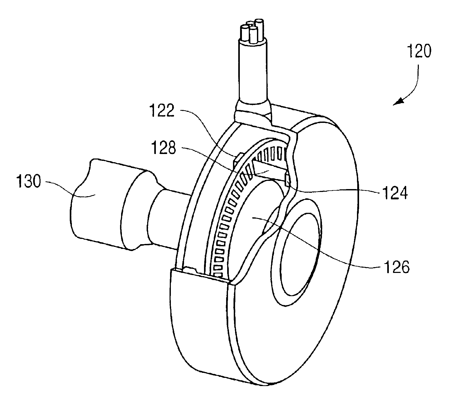
[0031]The present invention is concerned with the improvement of emitters, small detector arrays, and encoder disks in optical encoders. The encoders of the present invention have very small dimensions but provide high sensing resolution.

Emitters

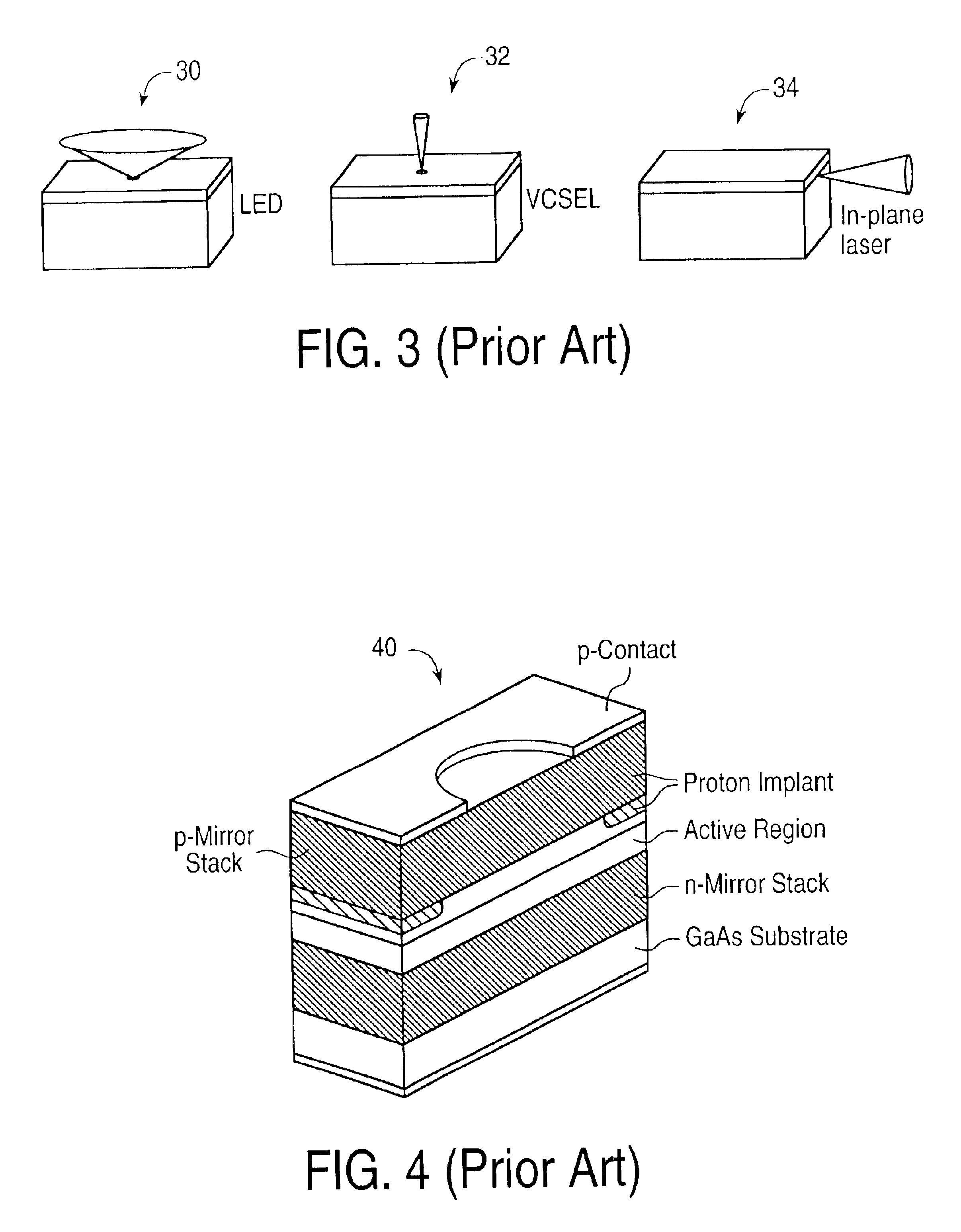
[0032]One aspect of the present invention provides a vertical cavity surface-emitting laser (VCSEL) for use as an emitter in an optical encoder. FIG. 3 illustrates an LED 30, a VCSEL 32, and an in-plane laser 34 with their different emission patterns. In comparison with LEDs and similar light emitting devices, a VCSEL is closer to the ideal optical encoder emitter. Commercialized recently to drive optical communication fibers, VCSELs are tiny lasers formed on the surface of gallium-arsenide semiconductor chips. They emit more power with less drive current than an LED and focus that power into a smaller area because their light is much less divergent than that of LEDs (though still not perfectly collimated). VCSELs also have higher efficiency...


PUM

PropertyMeasurementUnit
Timeaaaaaaaaaa
Angleaaaaaaaaaa
Energyaaaaaaaaaa

Abstract

Embodiments of high-resolution optical encoders having phased-array photodetectors and integrated on semiconductor chips. Emitters, detectors, and encoders disks are described which can be easily produced with semiconductor processes, such as a detector array provided with lens to collimate light and enhance detection. Integrated sensor chips include an array of photodetectors that receive energy from a beam emitted from an emitter and modulated by an encoder disk, analog-to-digital converters, state machines, counters, a communication module, a sensor processing unit, and a force computation unit. One embodiment includes low resolution and high resolution modes and an emitter controlled by sensor circuitry. A detector for an optical encoder can be provided on a single chip that includes a first array of photodetectors used for absolute sensing of a moving object, and a second array of photodetectors used for incremental sensing of the moving object.

Description

CROSS REFERENCE TO RELATED APPLICATIONS[0001]This application claims the benefit of and is a continuation of U.S. application Ser. No. 09 / 661,580, filed Sep. 14, 2000, now U.S. Pat. No. 6,564,168, which claims the benefit of U.S. Provisional Application No. 60 / 153,796, filed Sep. 14, 1999, each of which is assigned to the assignee of the present application, and each of which is incorporated in its entirety herein by reference.BACKGROUND OF THE INVENTION[0002]The present invention relates to sensing position and motion using sensor devices, and more specifically to sensing position and motion using optical encoder sensors.[0003]Encoders are useful in many applications. In one application, computer interface devices such as joysticks, mice, track balls, steering wheels, etc. make use of encoders to determine the position of a user manipulatable object (manipulandum) in a workspace of the user object, and provide the position information to a host computer that is connected to the int...

Claims


Application Information

Patent Timeline
IPC IPC(8): G01D5/36G01D5/347G01D5/26G01D5/34
CPCG01D5/34G01D5/34715G01D5/3473G01D5/366
Inventor HASSER, CHRISTOPHER J.
Owner IMMERSION CORPORATION
Why Eureka
Try Eureka