Heat transfer tube and a method of fabrication thereof

a heat transfer tube and heat transfer tube technology, applied in heat exchange apparatus, lighting and heating apparatus, corrosion prevention, etc., can solve the problems of increasing the pressure drop of the tubeside, reducing the required filling capacity of refrigerant, and a significant portion of the entire cost of the system, so as to achieve the highest driving temperature difference for the formation of bubbles and advantageous for the evaporation process

Inactive Publication Date: 2005-07-05
WIELAND WERKE AG
View PDF21 Cites 19 Cited by
  • Summary
  • Abstract
  • Description
  • Claims
  • Application Information

AI Technical Summary

Benefits of technology

[0016]A re-entrant secondary groove offers for the formation and stabilization of nucleation sites clearly more favorable conditions than the simple indentations suggested in EP 0 222 100. The position of the re-entrant secondary grooves near the primary base of the groove is particularly advantageous for the evaporation process since the wall superheat is the greatest at the base of the groove and therefore the highest driving temperature difference for the bubble formation is available thereat.

Problems solved by technology

Furthermore the required filling capacity of refrigerant is reduced which, in the case of the current predominantly used HFCs, can amount to a significant portion of the entire cost of the system.
An increase of the heat transfer on the inside of the tube results usually in an increase of the tubeside pressure drop.
However, more delicate tools are subjected to an increased danger of breakage and quicker wear.
Furthermore a decreasing fin pitch reduces the production speed of the tubes and consequently the manufacturing costs are increased.
However, the performance increases achievable by such structures in particular in the range of small heat fluxes no longer meet the demands of the market.
The indentations represent furthermore a weakening of the core wall of the tube and result in a reduction of the mechanical stability of the tube.

Method used


Image

  • Heat transfer tube and a method of fabrication thereof
  • Heat transfer tube and a method of fabrication thereof
  • Heat transfer tube and a method of fabrication thereof

Examples


embodiment 1 (fig.2)

Embodiment 1 (FIG. 2)

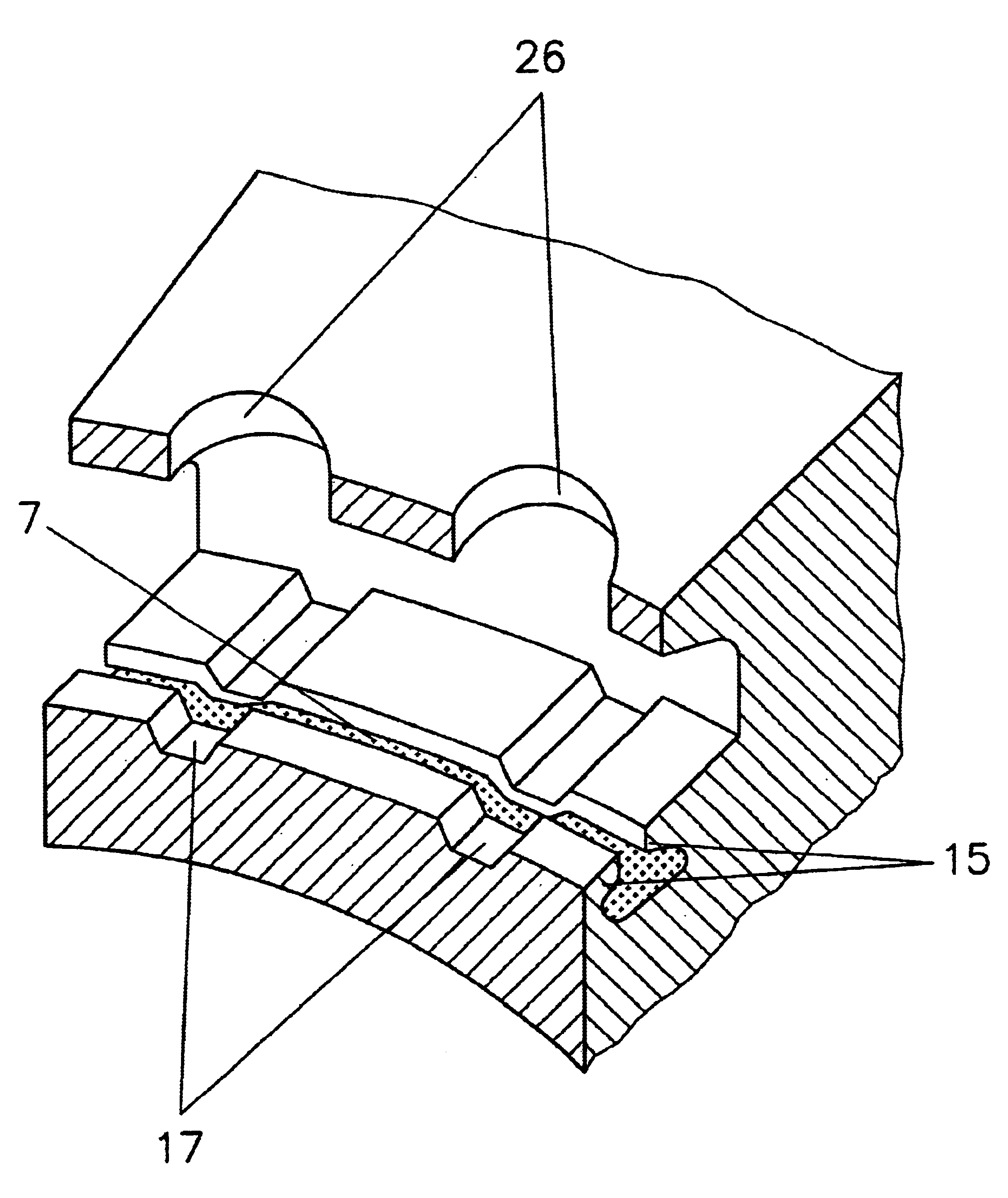
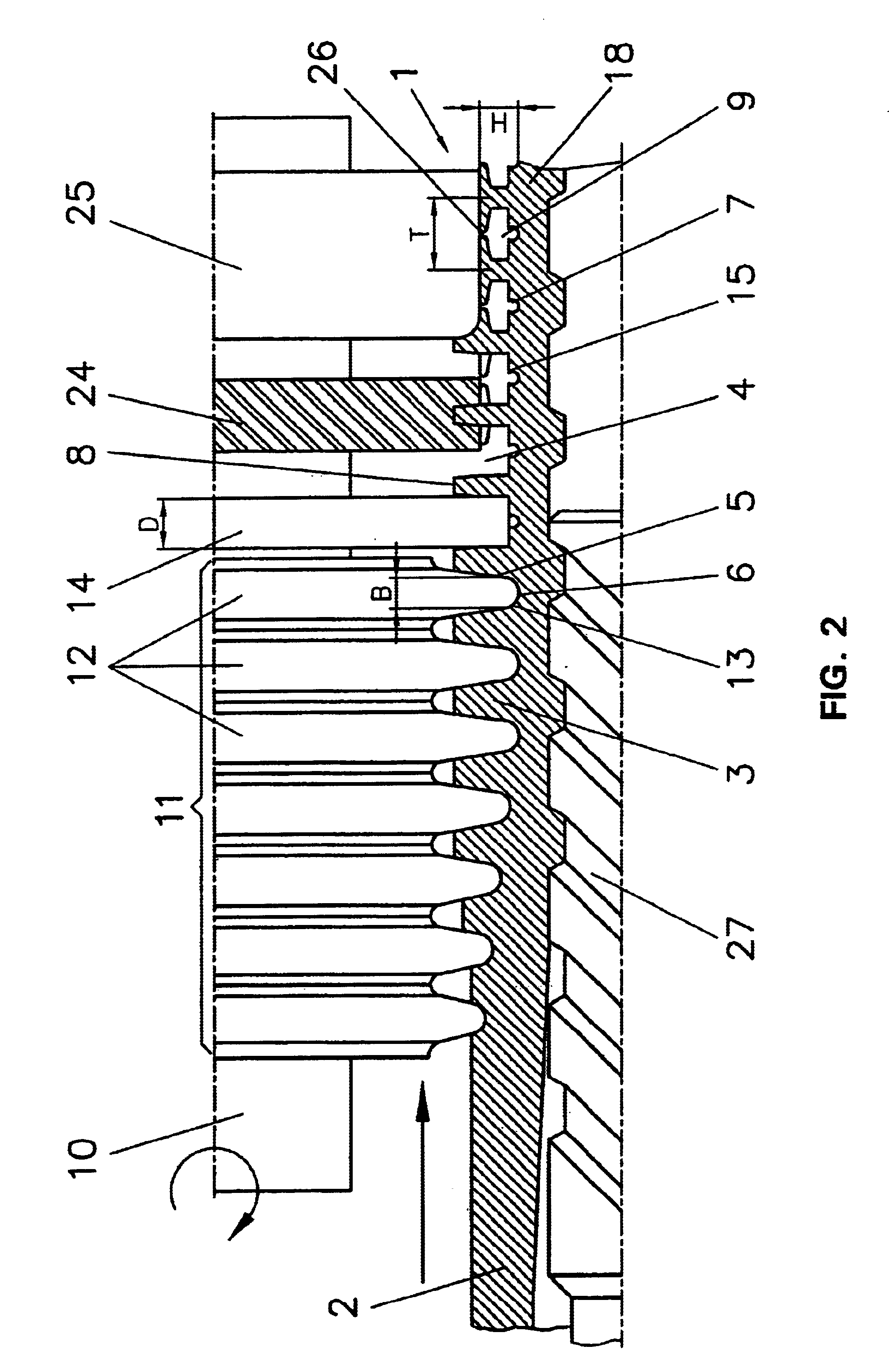
[0034]A cylindrical disk 14 is provided immediately after the last disk 12 of the rolling tool 11. The diameter of the disk 14 is less than the diameter of the largest rolling disk 12 which completes the forming of the fin 3. The thickness D of the cylindrical disk 14 is slightly greater than the width B of the primary groove 4 formed by the rolling disks 12, the width B of the primary groove 4 being measured at the point where the fin flank 5 transfers over into the radius area of the root of the fin 13. The thickness D of the cylindrical disk is typically 50% to 80% of the fin pitch T. The cylindrical disk 14 removes material from the fin flanks 5 and effects a movement thereof toward the base 6 of the primary groove 4. The removed material is shifted by suitably selecting the tool geometry in such a manner that it forms projections 15 (FIG. 3) above the base 6 of the primary groove 4 and thus a radially open closed off cavity 7 is formed directly at the base ...

embodiment 2 (fig.4)

Embodiment 2 (FIG. 4)

[0037]This embodiment represents an expansion of Embodiment 1. That is, a gear-like notching disk 16 is provided immediately after the cylindrical disk 14. The diameter of the notching disk 16 is greater than the diameter of the cylindrical disk 14, however, at most as great as the diameter of the largest rolling disk 12 of the rolling tool 11. The cavity 7 formed by the cylindrical disk 14 and extending in circumferential direction and having a uniform cross section is partitioned by indentations 17 (FIG. 5) formed in the radially outer roof thereof by the notching tool 16 at regular intervals in the circumferential direction. Thus, the heretofore uniform cross section of the circumferentially extending re-entrant secondary grooves 7 is now varied at regular intervals. The notching disk 16 can be straight or helically toothed.

[0038]Since the diameter of the gear-like notching disk 16 is not greater than the diameter of the largest rolling disk 12 of the rolling...

embodiment 3 (fig.6)

Embodiment 3 (FIG. 6)

[0039]A gear-like notching disk 19 is provided immediately after the last disk 12 of the rolling tool 11. The diameter of the notching disk 19 is at most as great as the diameter of the largest rolling disk 12. The thickness D′ of the notching disk 19 is slightly greater than the width B of the primary groove 4 formed by the rolling disks 12, the width B of the primary groove 4 being measured at the point where the fin flank 5 transfers over into the radiused portion of the root of the fin 13. The thickness D′ of the notching disk is typically 50% to 80% of the fin pitch T. The notching disk 19 can be straight or helically toothed. The notching disk 19 removes material from the area of the fin flanks 5 and from the radiused portion of the root of the fin 13 to thereby form spaced-apart indentations 20 (FIG. 7). The removed material is preferably shifted into the not worked area between the individual indentations 20 so that coined dams 21 are formed on the base ...


PUM

PropertyMeasurementUnit
equilibrium temperatureaaaaaaaaaa
metallicaaaaaaaaaa
lengthaaaaaaaaaa

Abstract

A metallic heat transfer tube, in particular for the evaporation of liquids from pure substances or mixtures on the outside of the tube. Fins are integrally formed on the outside of the tube. Recesses are arranged in the area of the base of the primary grooves and extend between the fins. The recesses are in the form of re-entrant secondary grooves. The mechanical stability of the tube is not negatively influenced because material is primarily removed from the fin flanks toward the base of the groove so that the re-entrant secondary grooves are radially open.

Description

FIELD OF THE INVENTION[0001]The invention relates to a metallic heat transfer tube, in particular for the evaporation of liquids from pure substances or mixtures on the outside of the tube.BACKGROUND OF THE INVENTION[0002]Evaporation occurs in many areas of air conditioning and refrigeration engineering and in process and energy engineering. Shell and tube heat exchangers are often used in this type of engineering, in which exchangers liquids from pure substances or mixtures evaporate on the outside of the tube, and thereby cool off a brine or water on the inside of the tube. Such devices are identified as flooded evaporators.[0003]By intensifying the heat transfer on the outside and the inside of the tube, it is possible to significantly reduce the size of the evaporator. This reduces the manufacturing costs of such devices. Furthermore the required filling capacity of refrigerant is reduced which, in the case of the current predominantly used HFCs, can amount to a significant port...

Claims


Application Information

Patent Timeline
Patent Type & Authority Patents(United States)
IPC IPC(8): B21C37/20B21C37/15F28F1/42F28F1/10B21H7/14F28F1/12F28F1/16F28F1/26F28F13/02
CPCB21C37/207F28F1/42F28F13/182F28F1/422Y10T29/4935Y10T29/49385
Inventor BEUTLER, ANDREASKNAB, MANFREDKNOEPFLER, ANDREASKRIEGSMANN, AXELMENZE, KLAUSSCHUEZ, GERHARDSCHWITALLA, ANDREAS
Owner WIELAND WERKE AG
Why Eureka
Try Eureka