
Automatic time signature-based video matching for a camera network

a technology of automatic video matching and camera network, which is applied in the field of automatic video matching for camera network, can solve the problems of tedious, expensive, and daunting tasks of the standard calibration process of each camera, and achieve the effect of maximizing the corresponden

Active Publication Date: 2016-01-14
AGT INTERNATIONAL INC
View PDF8 Cites 6 Cited by
  • Summary
  • Abstract
  • Description
  • Claims
  • Application Information

AI Technical Summary

Benefits of technology

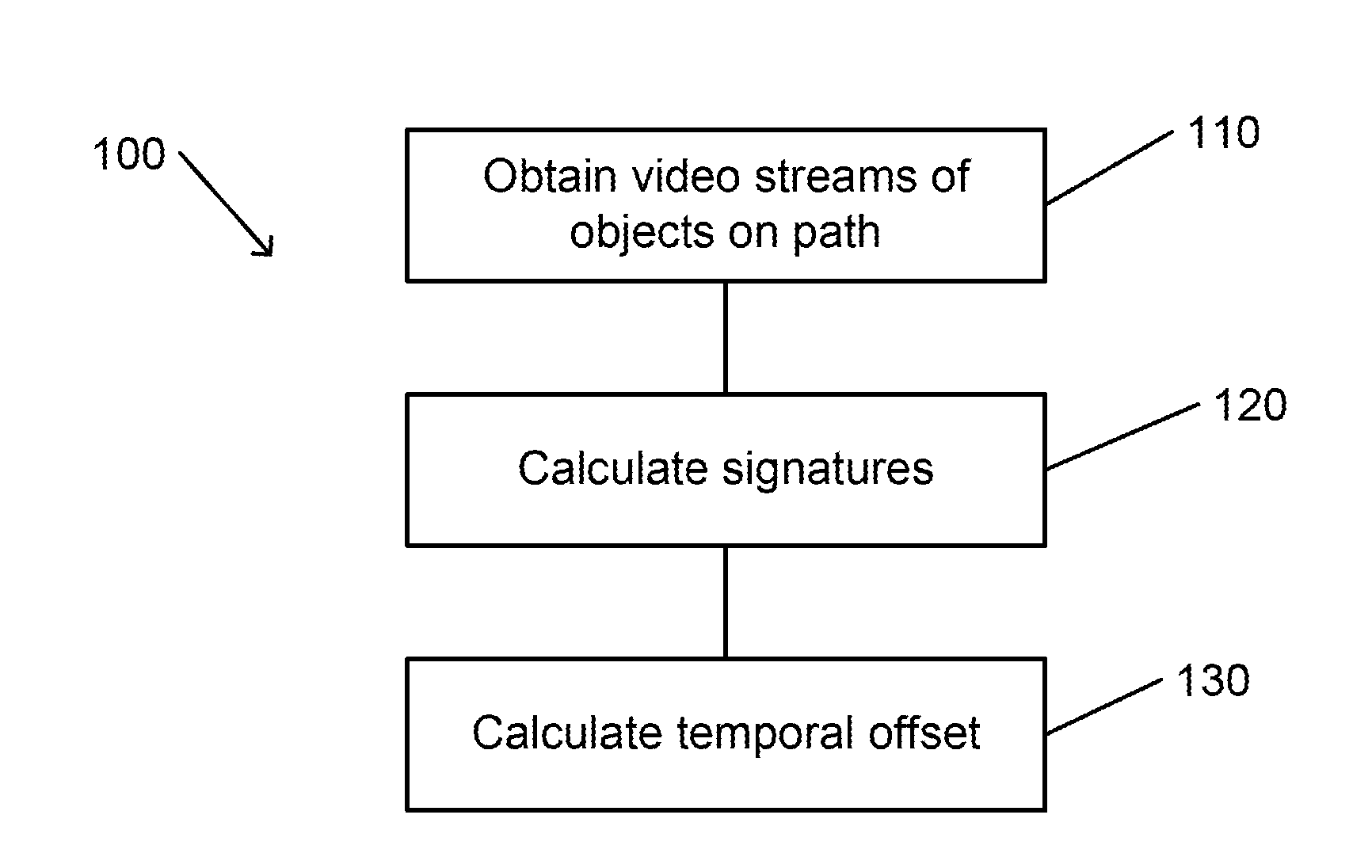
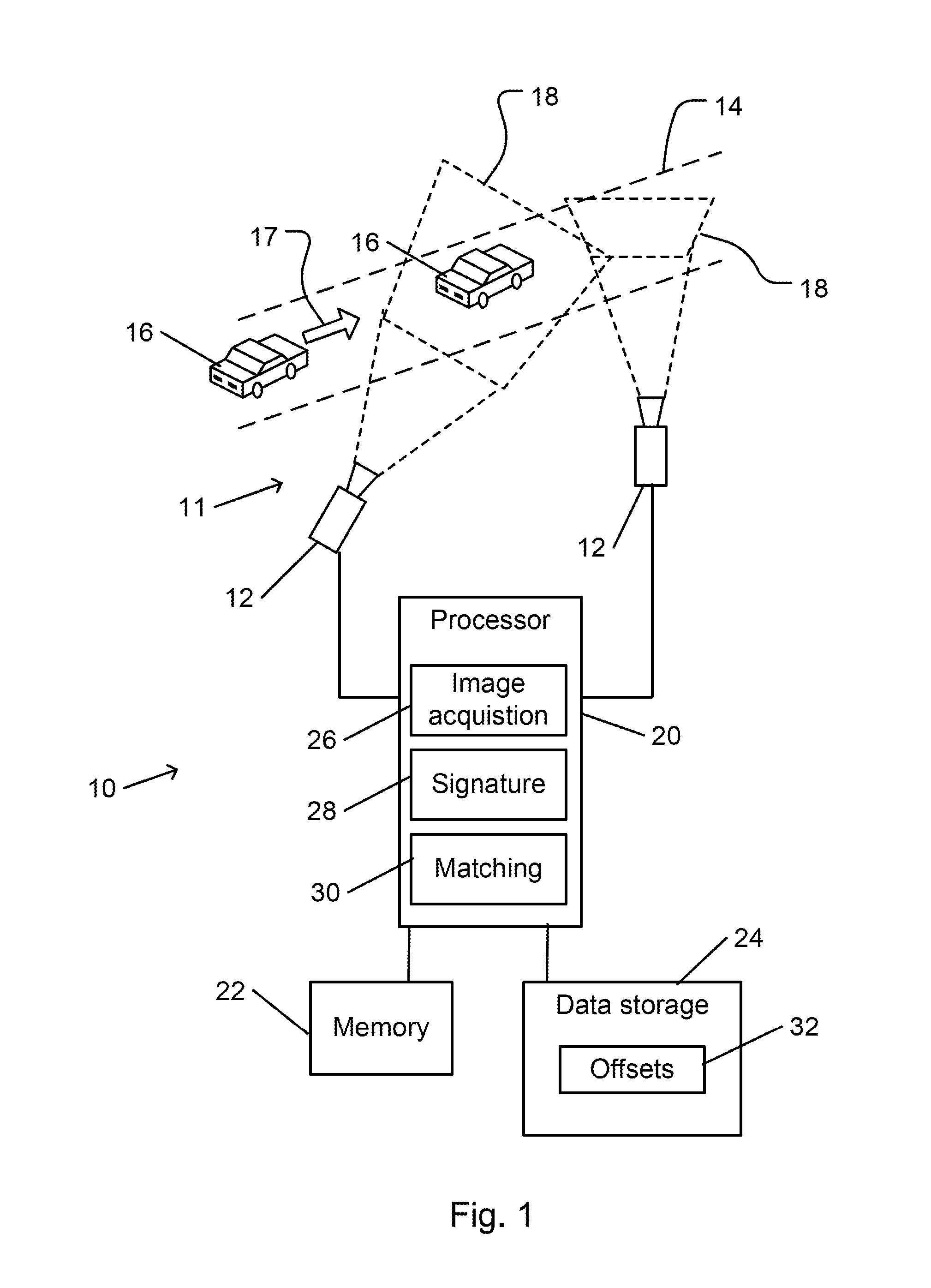
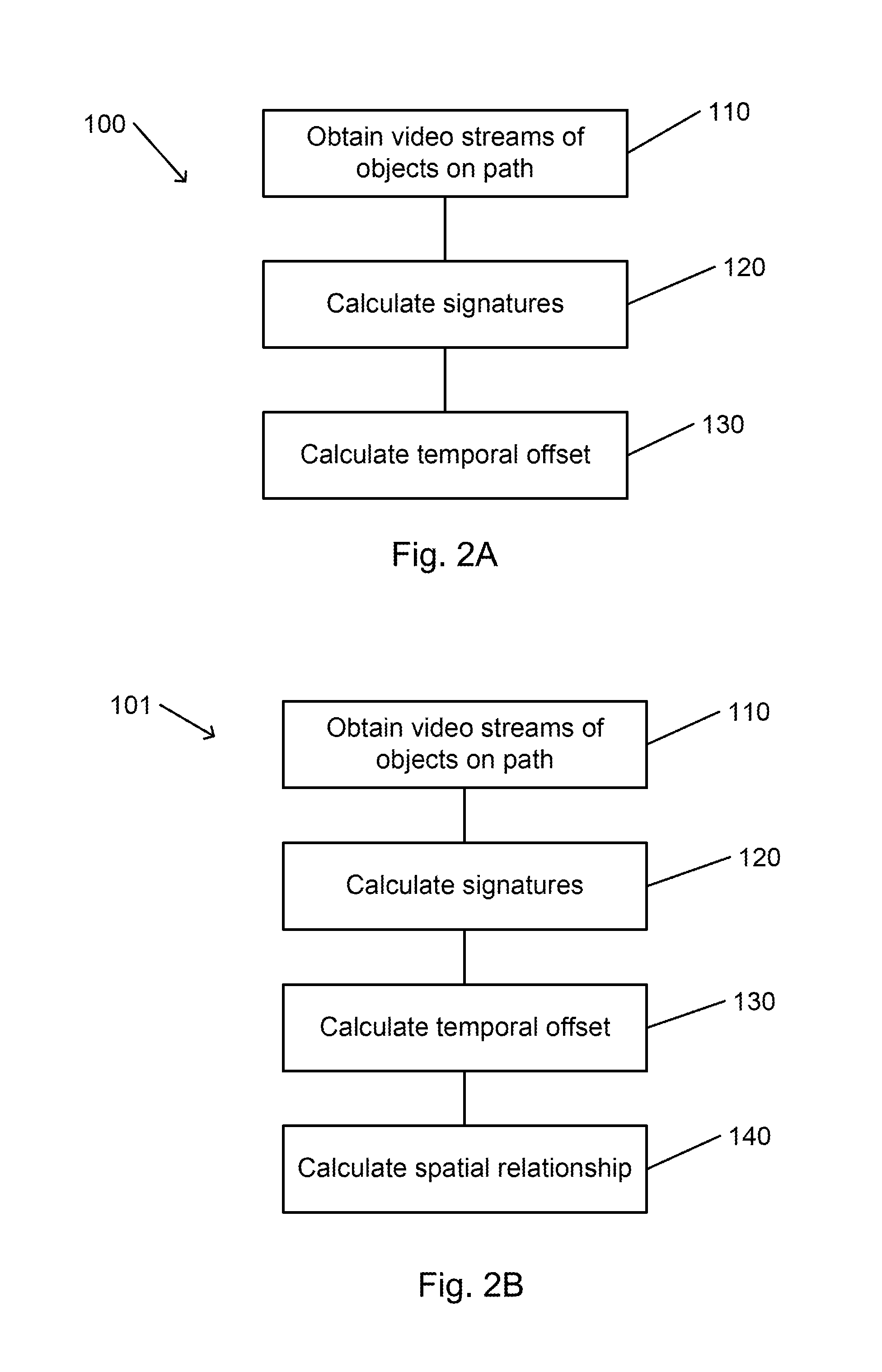
The present invention provides a method for automatically matching video streams from two cameras of a camera network, based on the timing of images of moving objects. This allows for the identification of identical moving objects captured by different cameras in the network. The method involves obtaining video streams, calculating time signatures for each stream, and calculating a temporal offset between them to maximize the correspondence between them. The technical effect is improved accuracy in identifying moving objects and events in a camera network.

Problems solved by technology

Performance of a standard calibration process for each of the cameras may represent a tedious, expensive, and daunting task.

Method used


Image

  • Automatic time signature-based video matching for a camera network
  • Automatic time signature-based video matching for a camera network
  • Automatic time signature-based video matching for a camera network

Examples


Embodiment Construction

[0036]In the following detailed description, numerous specific details are set forth in order to provide a thorough understanding of the invention. However, it will be understood by those of ordinary skill in the art that the invention may be practiced without these specific details. In other instances, well-known methods, procedures, components, modules, units and / or circuits have not been described in detail so as not to obscure the invention.

[0037]Although embodiments of the invention are not limited in this regard, discussions utilizing terms such as, for example, “processing,”“computing,”“calculating,”“determining,”“establishing”, “analyzing”, “checking”, or the like, may refer to an operation or process of a computer, a computing platform, a computing system, or other electronic computing device, that manipulates and / or transforms data represented as physical (e.g., electronic) quantities within the computer's registers and / or memories into other data similarly represented as ...


PUM


Abstract

A method for automatically matching video streams from two cameras of a camera network includes obtaining a video stream of frames that are acquired by each of the cameras. Each video stream includes images of moving objects. A time signature for each of the video streams is calculated. Each time signature is indicative of a time at which an image of one the objects is located at a predetermined part of the frame. A temporal offset of one of the signatures relative to the other signature is calculated such that, when applied to one of the signatures, a correspondence between the signatures is maximized. The temporal offset is applicable to video streams that are acquired by the two cameras to determine if a moving object that is imaged by one of the cameras is identical to a moving object that is imaged by the other camera.

Description

CROSS REFERENCE TO RELATED APPLICATIONS[0001]The present invention claims the priority benefit of U.S. provisional patent application No. 62 / 023,287 filed on Jul. 11, 2014, which is incorporated in its entirety herein by reference.FIELD OF THE INVENTION[0002]The present invention relates to camera networks. More particularly, the present invention relates to automatic video matching for a camera network, the video matching being based on time signatures.BACKGROUND OF THE INVENTION[0003]Traffic-monitoring cameras arranged along a road may be operated automatically to monitor traffic conditions. A typical traffic camera network includes cameras that are arranged along the length of the road and aimed to acquire video images of the road. Thus, the progress of a vehicle may be tracked as it travels along the road.[0004]For example, automatic monitoring of the progress of individual vehicles as they travel along the road may be helpful in determining traffic conditions on the road. Timel...

Claims


Application Information

Patent Timeline
IPC IPC(8): H04N5/04G06K9/00H04N5/44
CPCH04N5/04G06K9/00758H04N5/44G06V20/54G06V20/48
Inventor SCHLATTMANN, MARKUSDIENER, STEFAN
Owner AGT INTERNATIONAL INC
Learn More