Blade for a gas turbine engine

a gas turbine engine and blade technology, applied in the direction of engine manufacturing, climate sustainability, sustainable transportation, etc., can solve the problems of unfavorable failure, uneven pressure between the flank surface and the corresponding contact surface,

Inactive Publication Date: 2020-08-13
ROLLS ROYCE PLC
View PDF0 Cites 0 Cited by
  • Summary
  • Abstract
  • Description
  • Claims
  • Application Information

AI Technical Summary

Problems solved by technology

For blade roots having flank surfaces that are symmetrical about the longitudinal mid-plane of the blade root, e.g. because they run parallel to each other in the longitudinal direction, this results in an uneven pressure between the flank surfaces and the corresponding contact surfaces of the disc slot.
This may cause localised, high-stress regions and low-stress regions to form on the ends of the flank surfaces in the longitudinal directions, which have been found by the Applicant to be more susceptible to failure (e.g. cracking).

Method used


Image

  • Blade for a gas turbine engine
  • Blade for a gas turbine engine
  • Blade for a gas turbine engine

Examples


Embodiment Construction

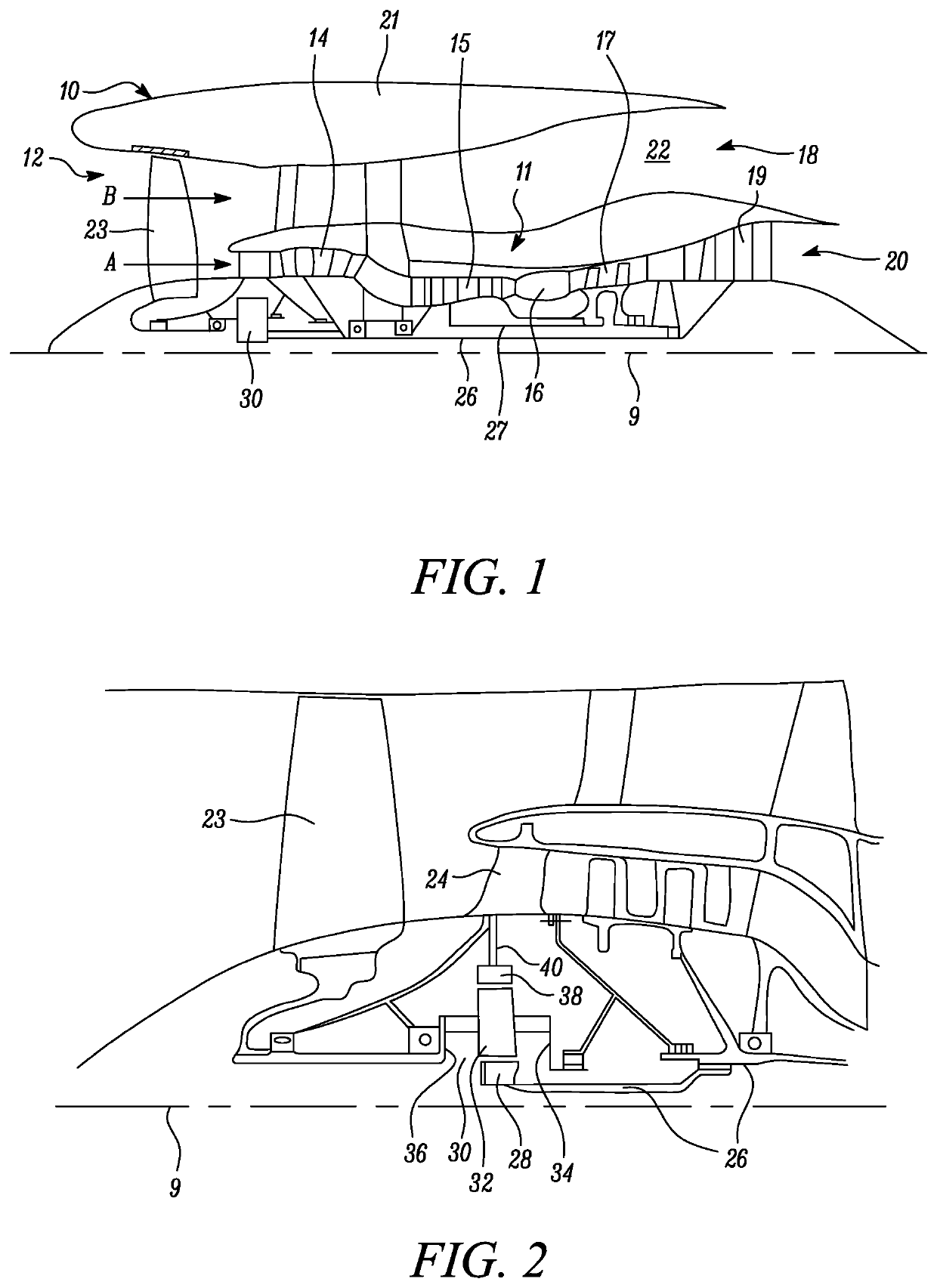
[0058]FIG. 1 illustrates a gas turbine engine 10 having a principal rotational axis 9. The engine 10 comprises an air intake 12 and a propulsive fan 23 that generates two airflows: a core airflow A and a bypass airflow B. The gas turbine engine 10 comprises a core 11 that receives the core airflow A. The engine core 11 comprises, in axial flow series, a low pressure compressor 14, a high-pressure compressor 15, combustion equipment 16, a high-pressure turbine 17, a low pressure turbine 19 and a core exhaust nozzle 20. A nacelle 21 surrounds the gas turbine engine 10 and defines a bypass duct 22 and a bypass exhaust nozzle 18. The bypass airflow B flows through the bypass duct 22. The fan 23 is attached to and driven by the low pressure turbine 19 via a shaft 26 and an epicyclic gearbox 30.

[0059]In use, the core airflow A is accelerated and compressed by the low pressure compressor 14 and directed into the high pressure compressor 15 where further compression takes place. The compres...


PUM


Abstract

There is disclosed a blade for a gas turbine engine comprising a blade root that is elongate in a longitudinal direction. The blade root comprises a first flank surface and a second flank surface on opposite sides of the blade root that are asymmetrical about a longitudinal mid-plane of the blade root.

Description

CROSS-REFERENCE TO RELATED APPLICATIONS[0001]This disclosure claims the benefit of UK Patent Application No. GB 1901683.1, filed on 7 Feb. 2019, which is hereby incorporated herein in its entirety.BACKGROUNDTechnical Field[0002]The present disclosure relates to a blade for a gas turbine engine.Description of the Related Art[0003]In a gas turbine engine, blades are typically mounted on a (rotor) disc of the gas turbine engine and extend generally radially from the disc. The disc is usually secured to a shaft of the gas turbine engine to allow rotation thereof (and of the blades) about a principal rotational axis of the gas turbine engine.[0004]In conventional bladed disc arrangements, a series of circumferentially arranged blades are mounted to the rotor disc. This is typically achieved by providing the blade with a blade root which fits within a slot, e.g. a bedding flank, provided in the disc. The blade root and slot have cooperating shapes such that the blade root may be received ...

Claims


Application Information

Patent Timeline
Patent Type & Authority Applications(United States)
IPC IPC(8): F01D5/30
CPCF01D5/3007F05D2250/38F05D2250/73F05D2240/80Y02T50/60
Inventor BATES, RONALD A.HUCKERBY, KARL S.WALKER, TOLAND
Owner ROLLS ROYCE PLC
Why Eureka
Try Eureka