Recip blade

a blade and recip technology, applied in the field of recip blades, can solve the problems of reducing and achieve the effects of reducing the mass per unit area, reducing the oscillating or whipping of the distal portion, and increasing the life of the blad

Inactive Publication Date: 2014-12-18
BLACK & DECKER INC
View PDF0 Cites 1 Cited by
  • Summary
  • Abstract
  • Description
  • Claims
  • Application Information

AI Technical Summary

Benefits of technology

[0014]One advantage of the present invention is that the at least one aperture or other means reduces the mass per unit area in the distal portion of the blade body which can, in turn, reduce the oscillating or whipping of the distal portion of the blade body and increase blade life.

Problems solved by technology

This type of lateral teeth loading, and / or the oscillation or whipping, can be unproductive and can give rise to lower blade life than desired.

Method used


Image

  • Recip blade
  • Recip blade

Examples


Embodiment Construction

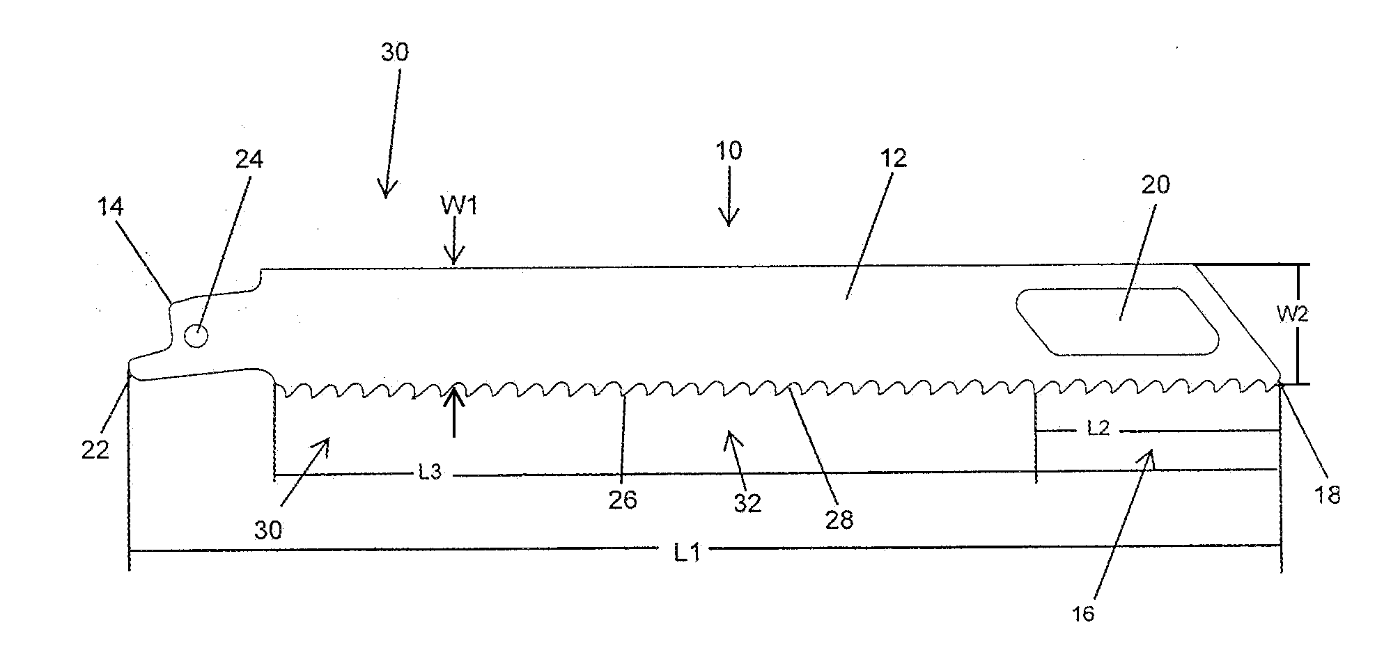
[0018]In FIG. 1, an embodiment of a recip blade representing the present invention is indicated generally by the reference numeral 10. The recip blade 10 comprises a blade body 12 and a tang 14 located at one end of the blade body 12. The blade body 12 includes a distal portion 16, which is located at an opposite end of the blade body 12 relative to the tang 14, and defines a tip 18 and at least one aperture 20 extending through the blade body 12. The tang 14 includes a tang stem 22 and a tang aperture 24 extending through the tang 14. The recip blade 10 also includes a cutting edge 26 that extends along the blade body 12, between the tang 14 and the tip 18. In some embodiments, the recip blade 10 is a metal cutting recip blade, and the cutting edge 26 includes a plurality of teeth 28 configured in a manner known to those of ordinary skill in the pertinent art for cutting metal work pieces. However, as may be recognized by those of ordinary skill in the pertinent art based on the te...


PUM

PropertyMeasurementUnit
lengthaaaaaaaaaa
lengthaaaaaaaaaa
lengthaaaaaaaaaa

Abstract

A recip blade has a blade body and a tang located at one end of the blade body. The blade body has a distal portion located on an opposite end of the blade body relative to the tang. The distal portion defines a tip and at least one aperture extending through the blade body. A cutting edge extends along the blade body between the tang and the tip.

Description

CROSS-REFERENCE TO RELATED APPLICATION[0001]This patent application claims benefit under 35 U.S.C. §119 to similarly-titled U.S. Provisional Patent Application No. 61 / 836,502, filed on Jun. 18, 2013, which is hereby incorporated by reference in its entirety as part of the present disclosure.FIELD OF THE INVENTION[0002]The present invention relates to recip blades, and more particularly, to recip blades with apertures or other features that reduce the mass per unit area in the distal portion of the blade in comparison to the remainder of the blade, and / or reduce oscillations or vibrations in the distal portion of the blade during cutting.BACKGROUND INFORMATION[0003]Shorter recip blades tend to last longer than longer recip blades when cutting the same applications. During cutting, the distal portions of the blades tend to oscillate or whip from side to side or laterally, and the longer the blade, the greater is the tendency of the distal portion to whip. When the oscillating or whipp...

Claims


Application Information

Patent Timeline
Patent Type & Authority Applications(United States)
IPC IPC(8): B23D49/10B23D61/12
CPCB23D61/123B23D49/10
Inventor GREEN, MATTHEW C.
Owner BLACK & DECKER INC
Why Eureka
Try Eureka