Refrigeration apparatus

a refrigeration apparatus and refrigerator technology, applied in the direction of lighting and heating apparatus, positive displacement liquid engines, liquid fuel engines, etc., can solve the problems of compressor unreliability, compressor insufficient lubrication, compressor oil concentration drop, etc., to reduce the standby power of refrigeration apparatus, reduce refrigerator oil concentration, and reduce refrigerator oil concentration

Active Publication Date: 2016-01-21
DAIKIN IND LTD
View PDF12 Cites 28 Cited by
  • Summary
  • Abstract
  • Description
  • Claims
  • Application Information

AI Technical Summary

Benefits of technology

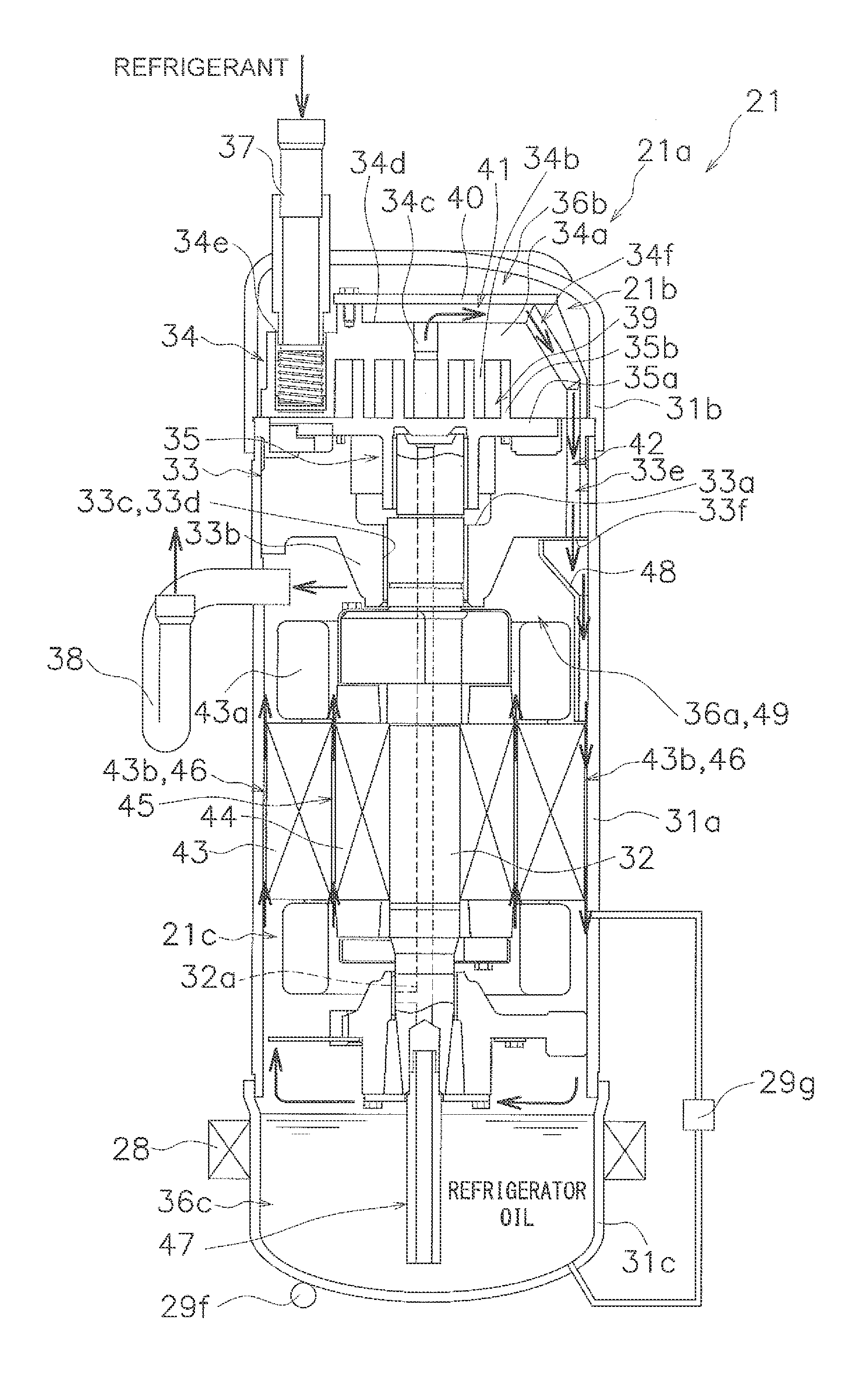
[0007]With heater control such as those of Patent Documents 1 to 3, standby power can be reduced more than in cases in which refrigerator oil inside a compressor is constantly heated while a refrigeration apparatus is stopped.
[0010]An object of the present invention is to provide a refrigeration apparatus that can minimize the standby power of the refrigeration apparatus as well as improve the reliability of the compressor while taking into account the decrease in refrigerator oil concentration (viscosity) caused by in-dome condensation.
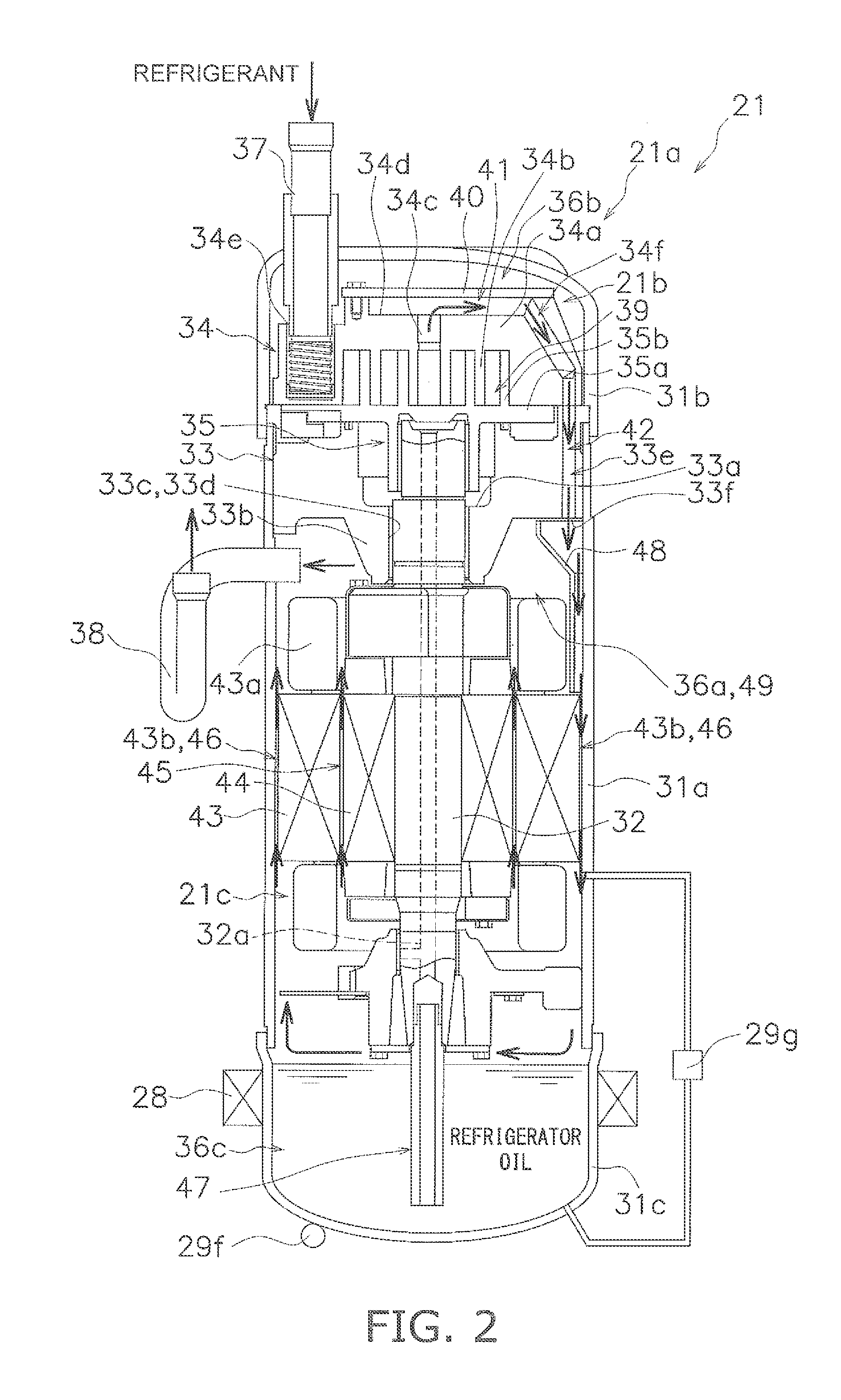
[0012]While the refrigeration apparatus is stopped, the refrigerator oil collected in the oil sump is heated herein so that the temperature of the refrigerator oil reaches a first oil temperature target value accounting for the decrease in the refrigerator oil concentration (viscosity) caused by in-dome condensation at the start of operation of the refrigeration apparatus, whereby the refrigerator oil concentration (viscosity) needed to lubricate the compressor can be maintained at the start of operation of the refrigeration apparatus even if in-dome condensation occurs. The power consumption of the heater, and consequently the standby power of the refrigeration apparatus, can be reduced by limiting the extent of the heating of the refrigerator oil collected in the oil sump to the first oil temperature target value.
[0013]It is thereby possible herein to minimize the standby power of the refrigeration apparatus as well as improve the reliability of the compressor while taking into account the decrease in the concentration (viscosity) of the refrigerator oil caused by in-dome condensation.
[0019]While the refrigeration apparatus is stopped, the refrigerator oil collected in the oil sump is heated until the temperature of the refrigerator oil reaches the oil temperature target value (i.e., the higher value of the first oil temperature target value and the second oil temperature target value) which takes into account the decrease in refrigerator oil concentration (viscosity) while the refrigeration apparatus is stopped as well as the decrease in refrigerator oil concentration (viscosity) caused by in-dome condensation at the start of operation of the refrigeration apparatus, whereby the concentration or viscosity of the refrigerator oil needed to lubricate the compressor can be maintained throughout the stopping of the refrigeration apparatus and the start of operation of the refrigeration apparatus.
[0020]It is thereby possible to minimize the standby power of the refrigeration apparatus as well as improve the reliability of the compressor while taking into account the decrease in refrigerator oil concentration (viscosity) caused by in-dome condensation and the decrease in refrigerator oil concentration (viscosity) while the refrigeration apparatus is stopped.

Problems solved by technology

When the liquid refrigerant produced by such in-dome condensation then dissolves in the refrigerator oil collected in the oil sump, there is a risk that when the refrigeration apparatus starts operating, the concentration (viscosity) of the refrigerator oil will decrease, the compressor will not be sufficiently lubricated, and the compressor will be unreliable.
However, because the refrigerant discharged from the compressor at the start of operation of the air-conditioning apparatus is low in temperature and near a state of saturation, providing the wall-surface heating passage still does not yield heating capacity sufficient to heat the wall surface of the casing at the start of operation of the air-conditioning apparatus, and it is difficult to suppress decreases in refrigerator oil concentration (viscosity) caused by in-dome condensation.

Method used


Image

  • Refrigeration apparatus
  • Refrigeration apparatus
  • Refrigeration apparatus

Examples


modification 1

[0114](4) Modification 1

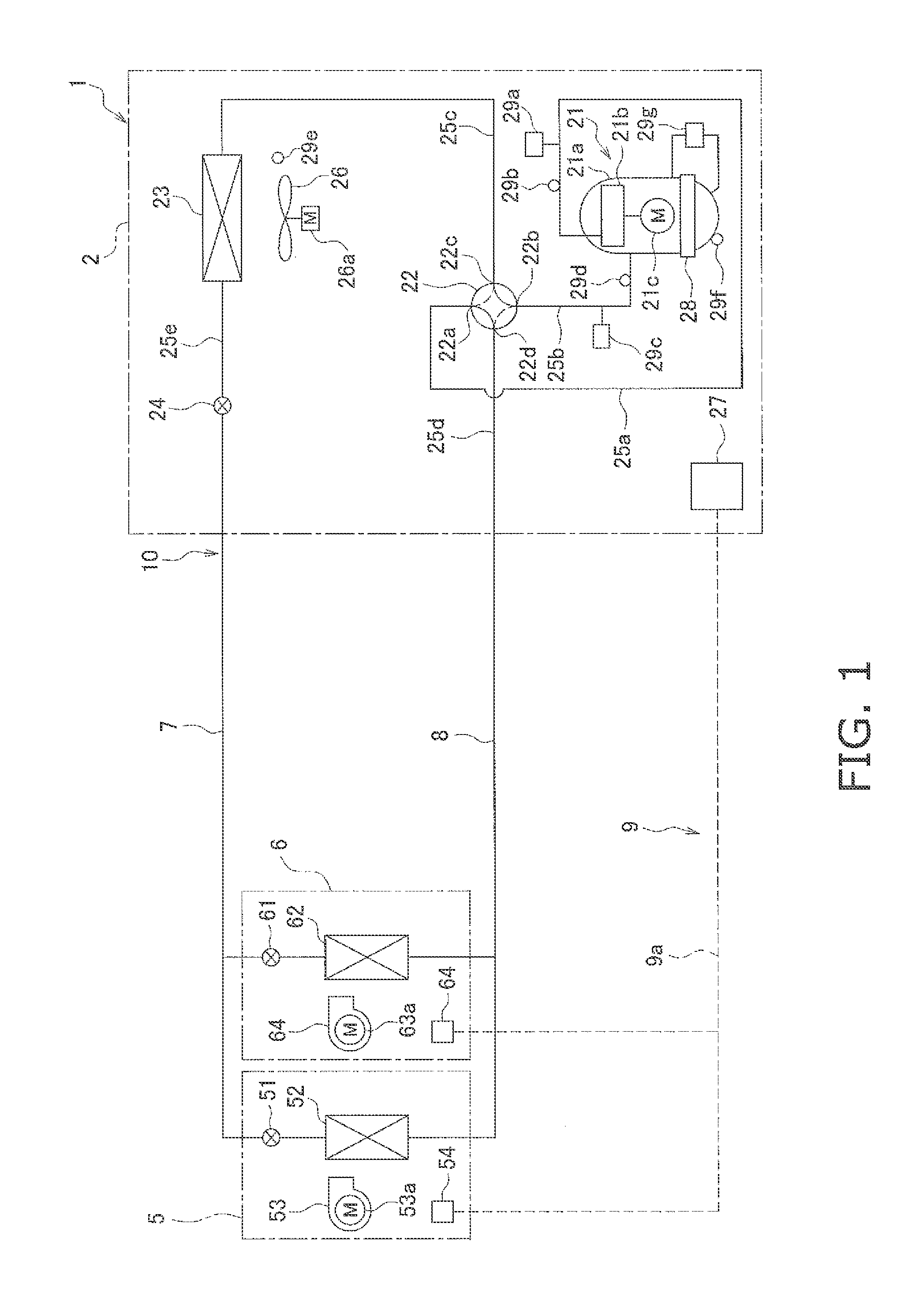
[0115]In the heating control of the refrigerator oil inside the compressor 21 in the above embodiment, the first oil temperature target value Ts1oil, which accounts for the decrease in refrigerator oil concentration (viscosity) caused by in-dome condensation at the start of operation of the air-conditioning apparatus 1 (at startup of the compressor 21), is designated as the oil temperature target value Tsoil. Heating control of the refrigerator oil inside the compressor 21 herein is performed with consideration given to the decrease in refrigerator oil concentration (viscosity) while the air-conditioning apparatus 1 (the compressor 21) is stopped, in addition to in-dome condensation.

[0116]Specifically, in steps ST11 and ST12, the controller 9 herein decides a second oil temperature target value Ts2oil that accounts for the refrigerator oil concentration (viscosity) while the air-conditioning apparatus 1 is stopped, in parallel with the process of deciding the...


PUM


Abstract

A refrigeration apparatus includes a compressor and a controller. The compressor has a casing and a compression element. Compressed refrigerant is sent out of the casing after being discharged into an internal space of the casing. An oil sump formed in the casing collects refrigerator oil. A heater heats the refrigerator oil collected. The controller controls the heater while the refrigeration apparatus is stopped so that a temperature of the refrigerator oil collected in the oil sump reaches a first oil temperature target value. The first oil temperature target value is set in order to keep a refrigerant condensation amount of the refrigerant equal to or less than an allowable condensation amount at which the concentration or viscosity of the refrigerator oil needed to lubricate the compressor can be maintained. The refrigerant condensation amount is caused by in-dome condensation at the start of operation of the refrigeration apparatus.

Description

TECHNICAL FIELD[0001]The present invention relates to a refrigeration apparatus, and particularly to a refrigeration apparatus comprising a compressor having a structure in which refrigerant compressed by a compression element is sent out of a casing after being discharged into an internal space of the casing in which an oil sump for collecting refrigerator oil is formed, a heater for heating the refrigerator oil collected in the oil sump, and a controller for controlling the heater.BACKGROUND ART[0002]Conventionally, refrigeration apparatuses have included air-conditioning apparatuses used to cool and heat room interiors of buildings or the like by performing a vapor-compression refrigeration cycle.[0003]In this type of refrigeration apparatus, when the temperature of the refrigerator oil is low while the refrigeration apparatus has stopped and the pressure of refrigerant in the compressor is under a certain condition, the amount of refrigerant dissolved in the refrigerator oil in ...

Claims


Application Information

Patent Timeline
Patent Type & Authority Applications(United States)
IPC IPC(8): F25B49/02F25B13/00F25B31/00
CPCF25B49/022F25B31/002F25B13/00F04C23/008F04B39/02F04C29/028F04C29/04F04C18/0215F04C2270/195F25B49/005F25B2313/0233F25B2400/01F25B2500/16F25B2500/27F25B2500/31F25B2700/1931F25B2700/1933F25B2700/21151F25B2700/21152F25B2700/21155F04B39/023
Inventor YURA, YOSHINORI
Owner DAIKIN IND LTD
Why Eureka
Try Eureka