
Mobile electronic device storage and charging cabinet

a mobile electronic device and charging cabinet technology, applied in the field of storage means, can solve the problems of inconvenience for the person in charge, easy theft easy damage so as to facilitate centralized management of mobile electronic devices, improve mobile electronic device charging efficiency, and save mobile electronic device charging time

Inactive Publication Date: 2016-01-21
CHUNG CHIAO HLDG
View PDF11 Cites 17 Cited by
  • Summary
  • Abstract
  • Description
  • Claims
  • Application Information

AI Technical Summary

Benefits of technology

The present invention is a mobile electronic device storage and charging cabinet that aims to save time and increase efficiency in charging mobile electronic devices while providing easy access. The main technical effects are the centralized management of mobile electronic devices, the reduction of charging time, and improved charging efficiency. Additionally, the invention includes a mounting space for power sockets, a jamb, and cable retainers to secure the transmission lines of battery chargers to prevent damage or interruption of connection.

Problems solved by technology

However, due to the characteristics of small size, light weight and high mobility, these mobile electronic devices can easily be damaged by impact.
The use of a large amount of mobile electronic devices brings inconvenience to the person in charge.
Further, these mobile electronic devices can be easily stolen.
However, conventional protective cases for mobile electronic device do not provide a charging function.
This provides an inevitable problem in charging storage mobile electronic devices.
In consequently, the overall effect of use and convenience would be restricted.
If there is a large amount of notebook computers or tablet computers to be electrically charged, the user must individually connect the battery chargers of the notebook computers or tablet computers to respective power sockets for charging, complicating the arrangement of the power cables and prolonging the charging time.

Method used


Image

  • Mobile electronic device storage and charging cabinet
  • Mobile electronic device storage and charging cabinet
  • Mobile electronic device storage and charging cabinet

Examples


Embodiment Construction

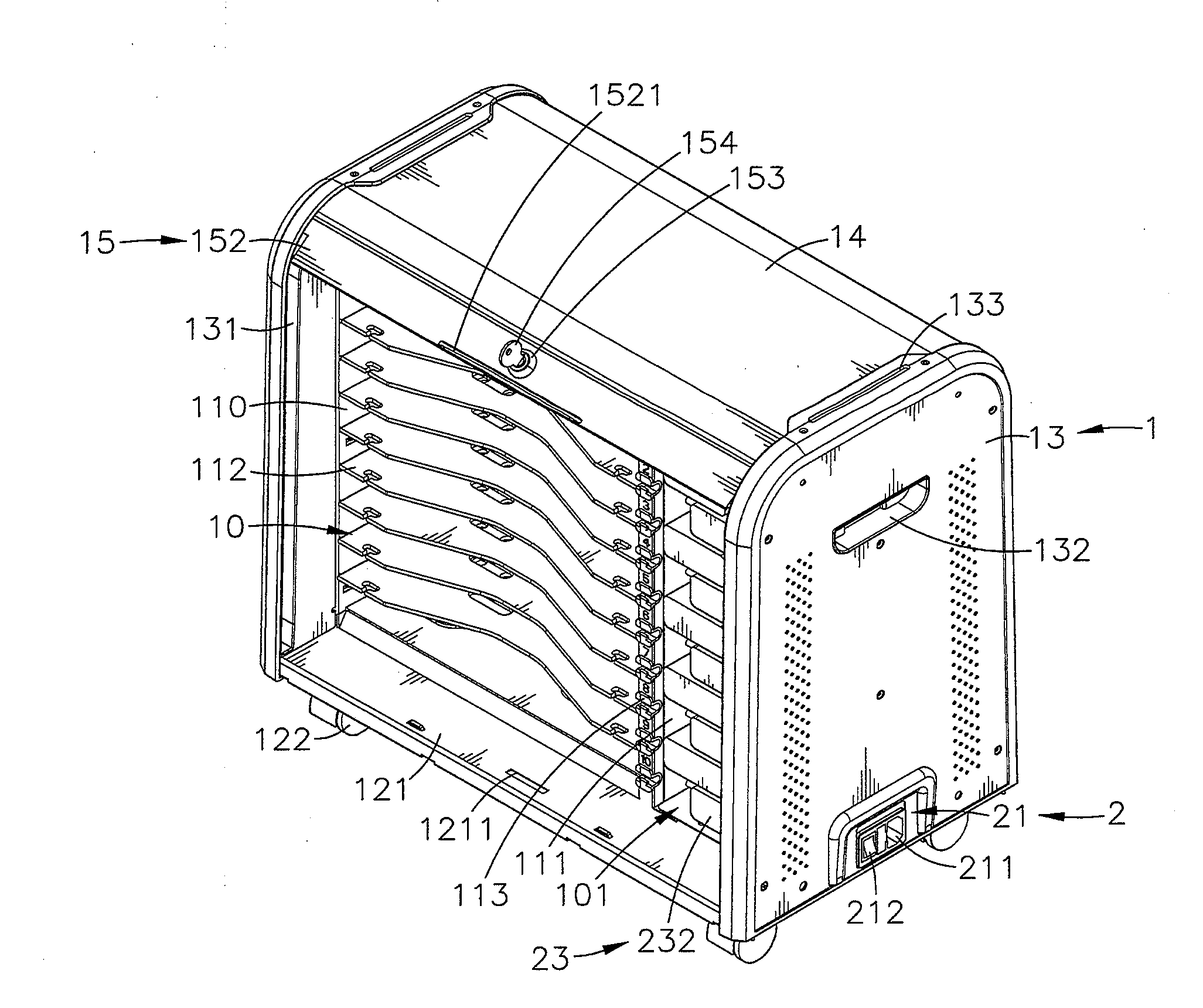
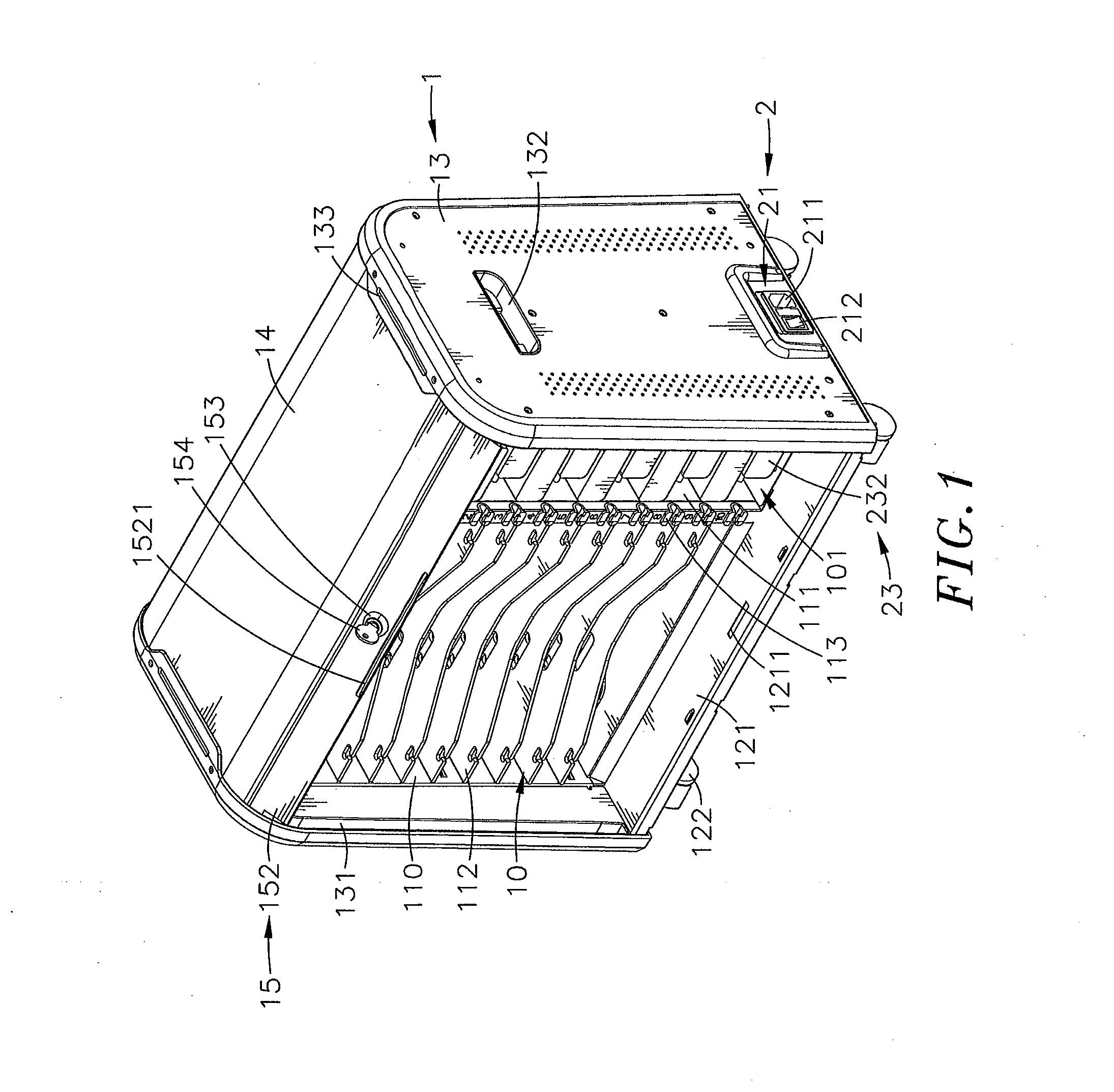
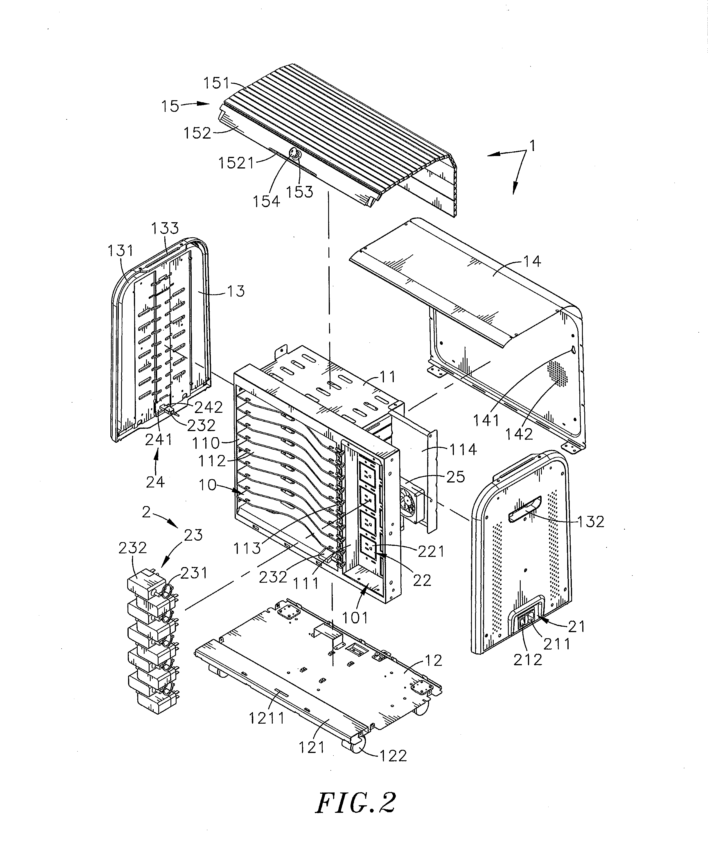
[0021]Referring to FIGS. 1-5, a mobile electronic device storage and charging cabinet in accordance with the present invention is shown. The mobile electronic device storage and charging cabinet comprises a body 1, and a power supply unit 2.

[0022]The body 1 comprises an inner housing 11, a bottom panel 12, two upright side panels 13, an outer cover panel 14, and a sliding door 15. The inner housing 11 comprises a forward-facing accommodation chamber 10, a mounting space 101 defined in a front side thereof and disposed at one lateral side of the accommodation chamber 10, a jamb 111 located in the front side between the accommodation chamber 10 and the mounting space 101, a plurality of horizontal partition plates 112 mounted in the accommodation chamber 10 at different elevations and dividing the accommodation chamber 10 into a plurality of vertically spaced storage compartments 110, a plurality of cable retainers 113 mounted in a front side of the jamb 111 at different elevations co...


PUM


Abstract

A mobile electronic device storage and charging cabinet includes a body including an inner housing surrounded by a bottom panel, two upright side panels and an outer cover panel and having storage compartments defined therein for accommodating mobile electronic devices individually and a sliding door movable along tracks at the upright side panels to close or open the inner housing, and a power supply unit including a power input module for power input, a power socket module mounted in the inner housing and electrically connected to the power input module and battery chargers respectively electrically connected to the power socket module and adapted for charging storage mobile electronic devices. Thus, the invention facilitates centralized management of mobile electronic devices, saves mobile electronic device charging time, improves mobile electronic device charging efficiency and enhances ease of use.

Description

BACKGROUND OF THE INVENTION[0001]1. Field of the Invention[0002]The present invention relates to storage means for use in a desk or the like for storing mobile electronic devices, and more particularly to a mobile electronic device storage and charging cabinet, which comprises an inner housing defining therein multiple compartments for storing mobile electronic devices individually, a sliding door movable to open or close the inner housing, and a power supply unit for charging all storage mobile electronic devices, facilitating mobile electronic device management and, improving mobile electronic device charging efficiency.[0003]2. Description of the Related Art[0004]With fast development of electronic and multimedia technologies, advanced and sophisticated notebook computers, tablet computer, smart phone, PDA and many other mobile electronic devices have been continuously created and appeared on the market. These mobile electronic devices have the characteristics of small size, ligh...

Claims


Application Information

Patent Timeline
IPC IPC(8): H02J7/00
CPCH02J7/0027H02J7/0044
Inventor TSOU, WEN-SHENG
Owner CHUNG CHIAO HLDG
Learn More