

HVDC (high voltage direct current controller) and UPFC (unified power flow controller) system based on modularized multi-level converter
A modular multi-level converter technology, applied in the field of HVDC and UPFC systems, can solve the problems of non-centralized management and control, low utilization rate of equipment, repeated investment in construction, etc., to improve utilization rate, increase device capacity, Ease of centralized management and control
- Summary
- Abstract
- Description
- Claims
- Application Information
AI Technical Summary
Problems solved by technology
Method used
Image

Examples
Embodiment 1
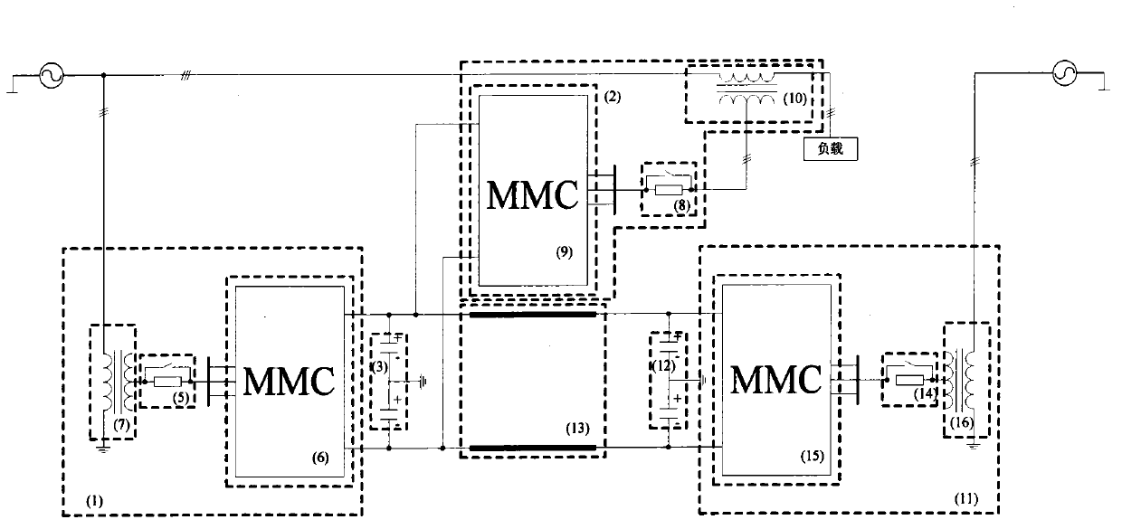
[0043] This embodiment provides an HVDC and UPFC system based on a modular multilevel converter, and its topology is as follows image 3 As shown, it includes a converter device 1, a converter device 2, a converter device 11, a grounding circuit 3, a grounding circuit 12 and a DC transmission line 13;
[0044] One end of the converter device 1 is connected in series with the power grid, and the other end is connected in parallel with the grounding circuit 3; both ends of the grounding circuit 3 are divided into at least two branches, one of which is connected to the converter device 2 and then connected to the power grid to form a A group of unified power flow controllers UPFC; the second branch is connected to the grid through the DC transmission line 13 and the converter device 11 to form a group of flexible direct current transmission HVDC; the DC transmission line 13 and the converter device 11 is connected in parallel with ground capacitor 12.
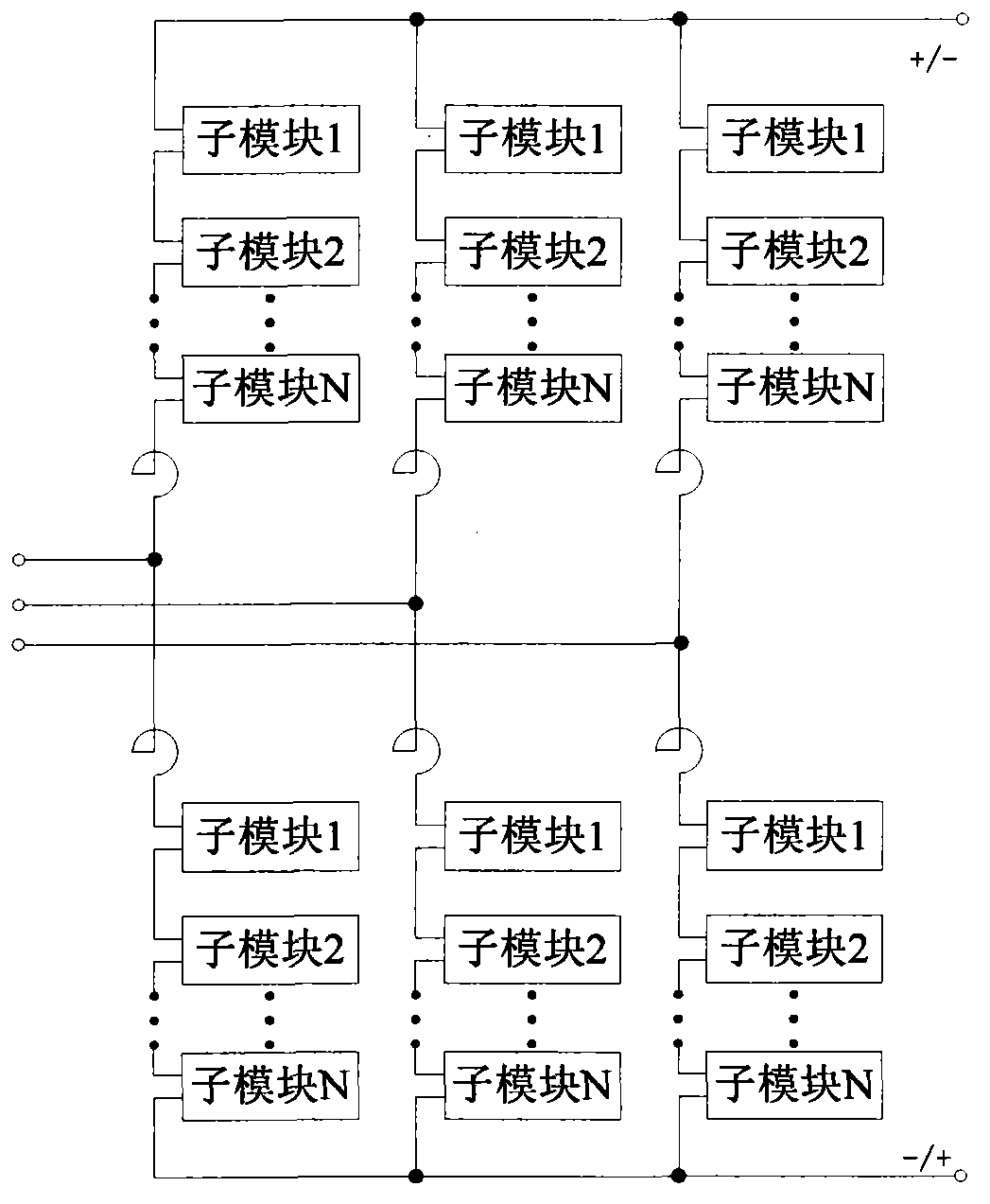
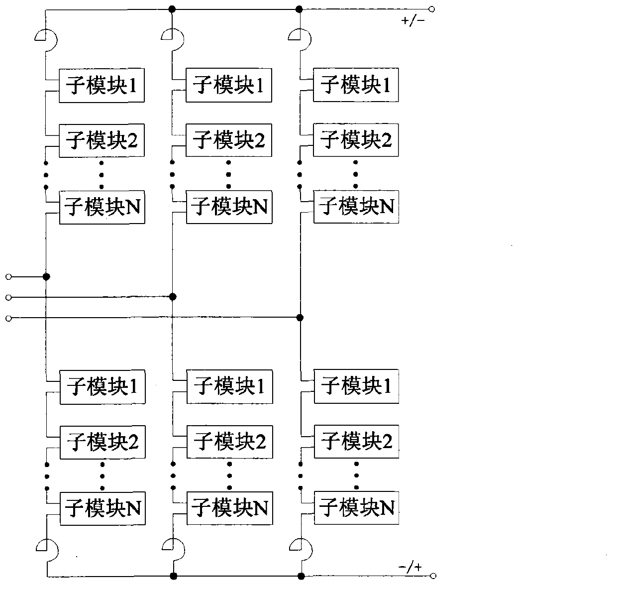
[0045] Among them, each d...
Embodiment 2
[0056] This embodiment is basically the same as Embodiment 1, but the difference lies in:
[0057] In order to control the connection and exit of the converter device 2 in this embodiment, a bypass switch 4 is connected in parallel at both ends of the transformer 10 in this embodiment, as Image 6 shown.
PUM
 Abstract
Description
Claims
Application Information