Container drying device

a drying device and container technology, applied in drying machines, drying machines with non-progressive movements, drying solid materials, etc., can solve the problems of low capacity, low upper limit of machine capacity, time-consuming, energy-consuming and expensive cleaning procedures, etc., and achieve high centrifugal force during rotation and robust and sturdy

Inactive Publication Date: 2015-08-04
SEMI STAAL
View PDF15 Cites 0 Cited by
  • Summary
  • Abstract
  • Description
  • Claims
  • Application Information

AI Technical Summary

Benefits of technology

[0011]By providing the booths arranged substantially in parallel with each other in the container drying device it becomes possible to load and unload stacks of crates into and from the at least two booths simultaneously, which in turn increases the capacity of the device considerably.
[0033]Thereby a container drying device is provided in which the stacks of containers may be retained in a particularly robust manner during rotation, which in turn provides for a particularly robust and sturdy container drying device capable of withstanding very high centrifugal forces during rotation.

Problems solved by technology

Most known container drying machines are capable of processing only one or very few containers at the time or at most one stack of containers at the time, and thus have very low capacities, which results in a time consuming, energy consuming and expensive cleaning procedure.
These types of container drying machines may dry several stacks of containers simultaneously, but nevertheless have several drawbacks.
Firstly, only one stack of containers may be loaded into or unloaded from the machine at the time.
Thereby, the capacity of the machine, i.e. the number of containers treated per time unit, has a relatively low upper limit, and the cleaning procedure becomes correspondingly more time consuming.
Secondly, both the construction of the machines itself, being rather complex and thus correspondingly heavy, and the arrangement of the stacks of containers in the machines result in a high energy consumption and a high exposure of less durable parts of the machine to stress caused by the centrifugal forces acting during rotation of the machine.

Method used


Image

  • Container drying device
  • Container drying device
  • Container drying device

Examples


Embodiment Construction

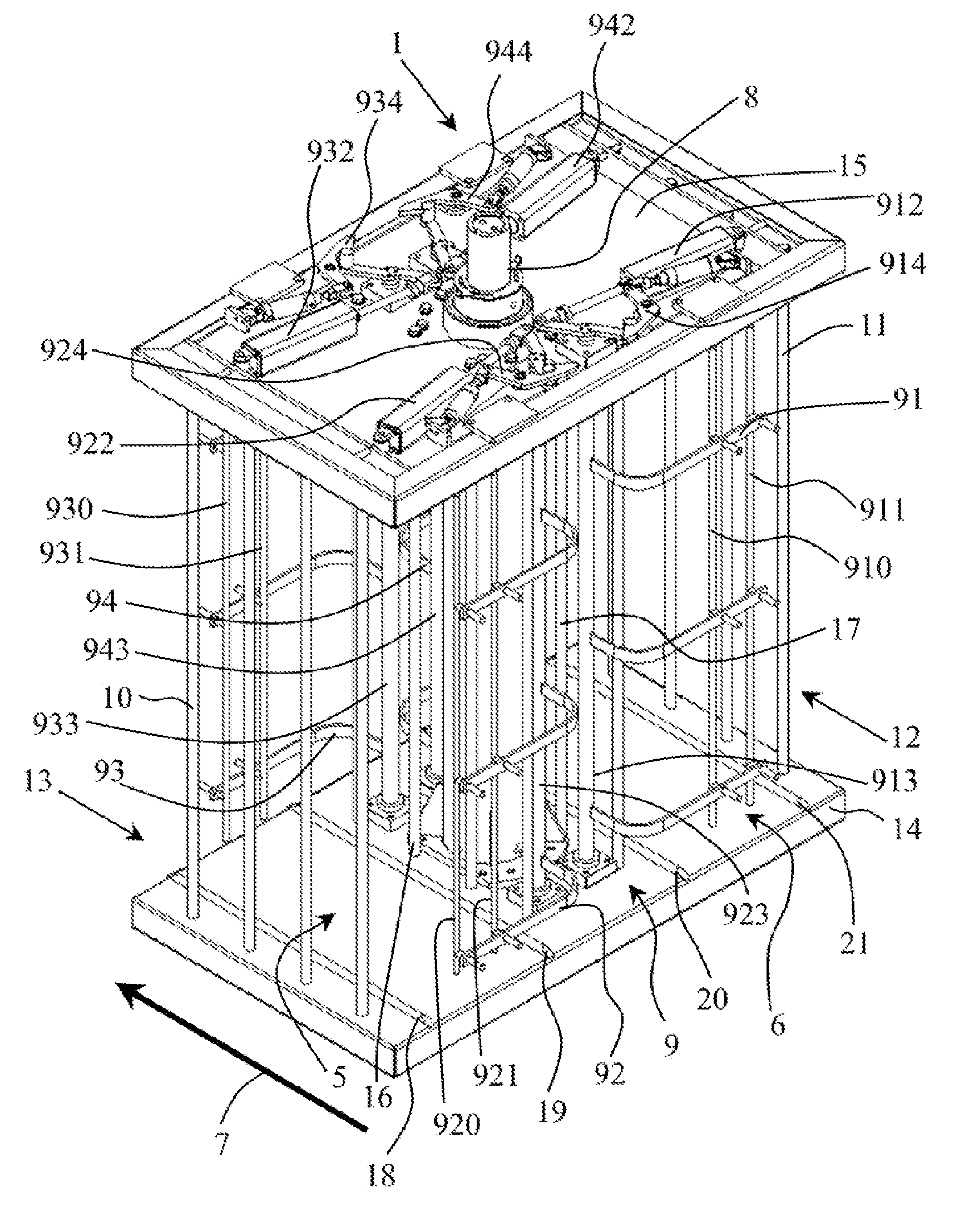
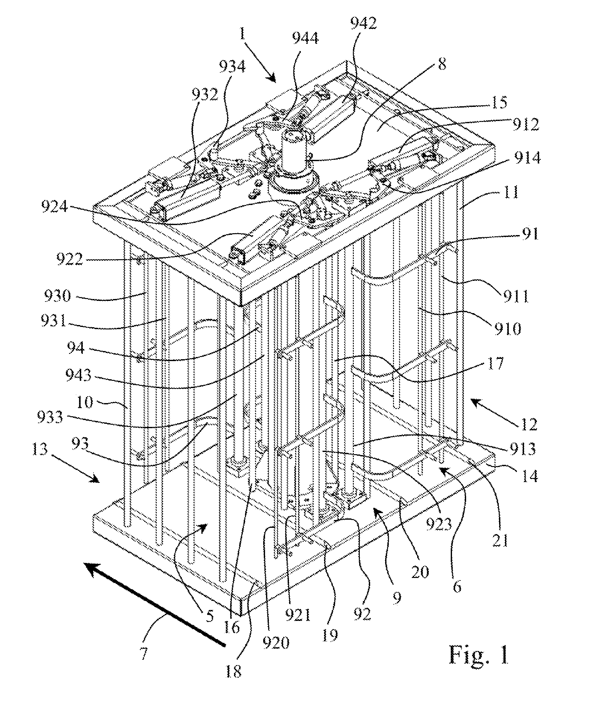
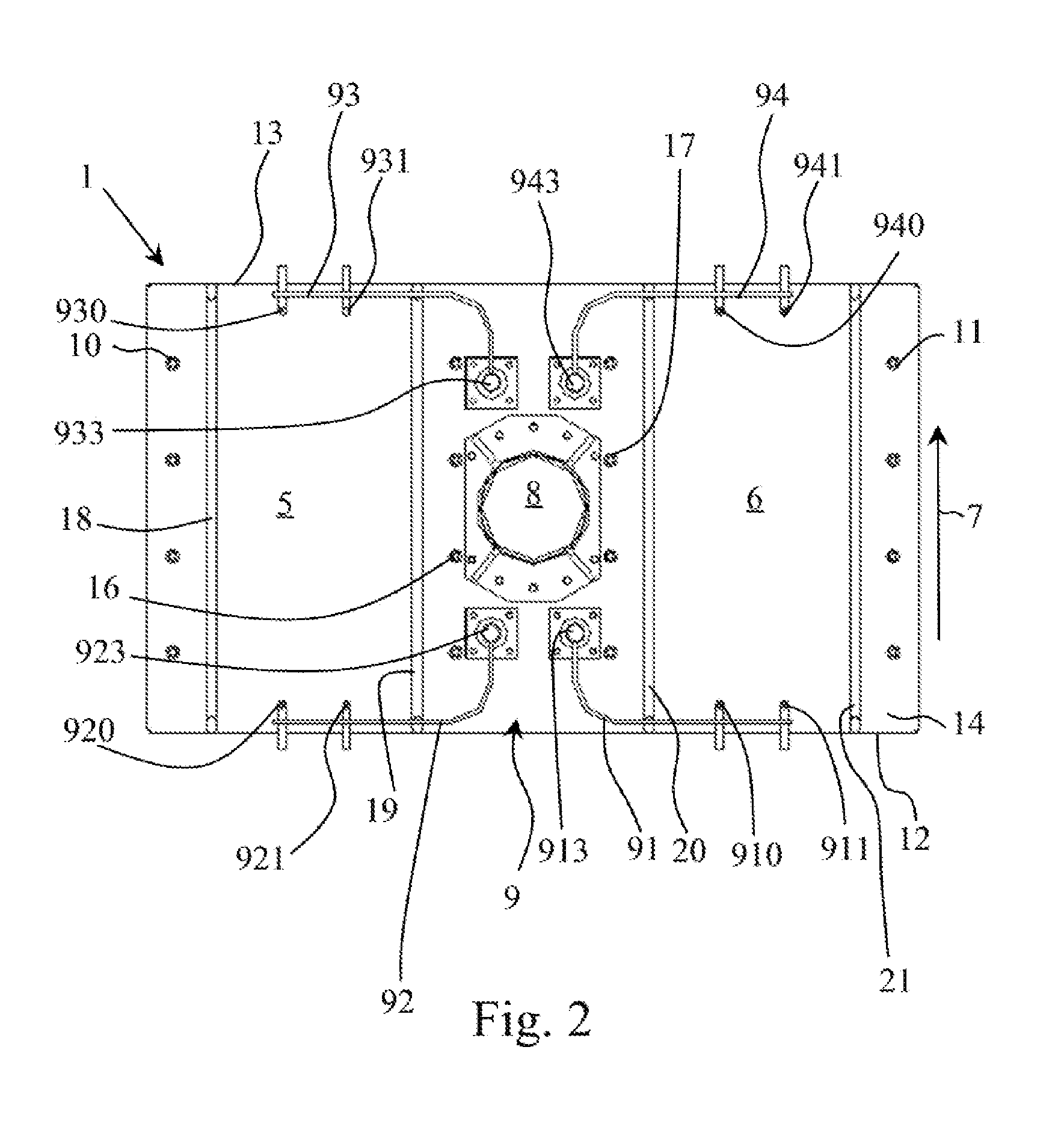
[0048]FIGS. 1 to 4 show an embodiment of a container drying device 1 according to the invention. The container drying device 1 comprises two booths 5, 6, an axis of rotation 8 about which the container drying device is rotatable and a closing device 9.

[0049]With reference also to FIGS. 5 and 6, each booth 5, 6 is adapted to receive at least one stack of containers 2, 3, 4 in a use position of the container drying device 1. The stacks of containers 2, 3, 4 to be dried are loaded into the at least two booths in a loading direction 7 through a first side 12 of the container drying device 1. Similarly, upon completion of a drying cycle the now dry stacks of containers are unloaded from the at least two booths 5, 6 in the loading direction 7 through a second side 13 of the container drying device 1 opposite the first side 12. In an alternative embodiment, it is feasible that loading and unloading of the stacks of containers may take place from the same side 12 or 13 of the container dryi...


PUM


Abstract

Container drying device of the spin-dryer type includes at least two booths, each being adapted to accommodate at least one stack of containers, the at least one stack of containers being loaded into the at least two booths in a loading direction, an axis of rotation about which the container drying device being rotatable, extending in a direction substantially perpendicular to the loading direction, and being arranged centrally in the container drying device; and a closing device being movable between a closed position in which the closing device closes the at least two booths at least partially and an open position in which the at least one stack of containers may be loaded into and / or removed from each of the at least two booths, the at least two booths being arranged excentrically, symmetrically on opposite sides of the axis of rotation and substantially in parallel with each other.

Description

PRIORITY STATEMENT[0001]The present application hereby claims priority under 35 U.S.C. §119 to Danish patent application number PA 2013 70239 filed 30 Apr. 2013, the entire contents of which are hereby incorporated herein by reference.INTRODUCTION[0002]The present application relates to a container drying device of the spin-dryer type for drying stacks of containers, particularly containers for distributing foodstuffs and / or containers for distributing medical or pharmaceutical products.BACKGROUND ART[0003]As used herein the term “container” is intended to cover containers for distributing foodstuffs, such as boxes, crates or cases for containing e.g. bread, fruit, milk in cartons, meat or the like, and / or containers for distributing medical or pharmaceutical products e.g. from a manufacturer to the retail stage of a distribution chain, the containers being re-useable. Preferably, but not exclusively, such containers are of the type comprising openings, such as a grating-like struct...

Claims


Application Information

Patent Timeline
Patent Type & Authority Patents(United States)
IPC IPC(8): F26B25/00F26B11/00F26B5/08F26B25/12
CPCF26B11/00F26B5/08F26B25/003F26B25/12
Inventor JORGENSEN, JOHN
Owner SEMI STAAL
Why Eureka
Try Eureka