Oral care appliance using pulsed fluid flow

a technology of pulsed fluid flow and oral care appliance, which is applied in the field of oral care appliance using pulsed fluid flow, can solve the problems of needing dual power sources, use of separate liquid and gas delivery systems,

Active Publication Date: 2016-01-28
KONINKLJIJKE PHILIPS NV
View PDF2 Cites 32 Cited by
  • Summary
  • Abstract
  • Description
  • Claims
  • Application Information

AI Technical Summary

Problems solved by technology

Use of separate liquid and gas delivery systems typically have some problems with timing, as well as space constraints and the need for dual power sources.

Method used


Image

  • Oral care appliance using pulsed fluid flow
  • Oral care appliance using pulsed fluid flow
  • Oral care appliance using pulsed fluid flow

Examples


Embodiment Construction

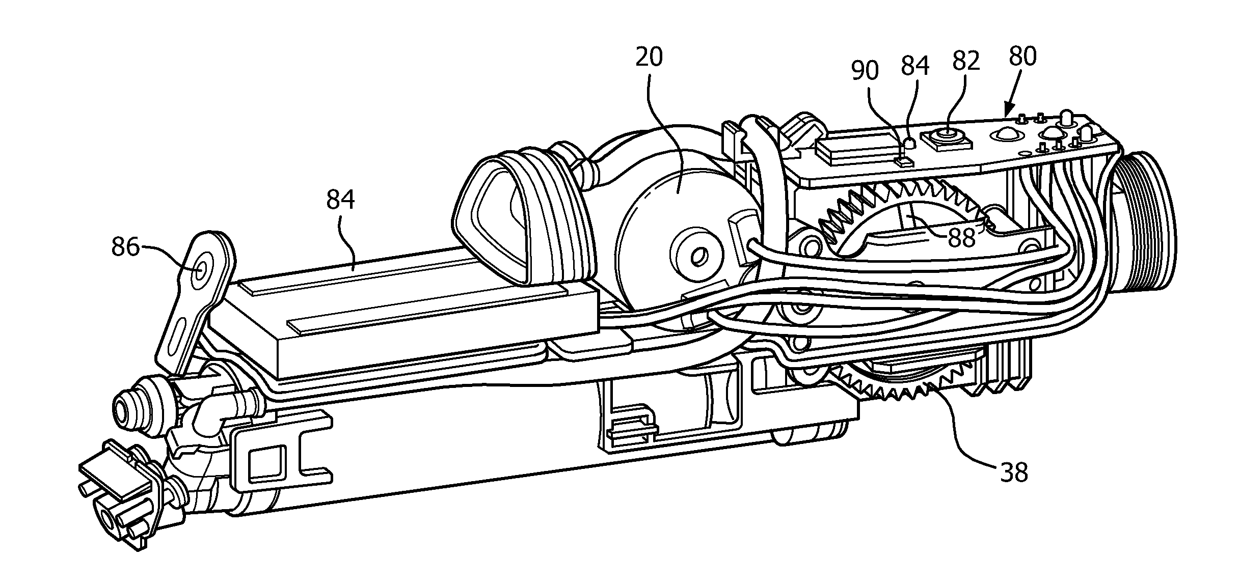
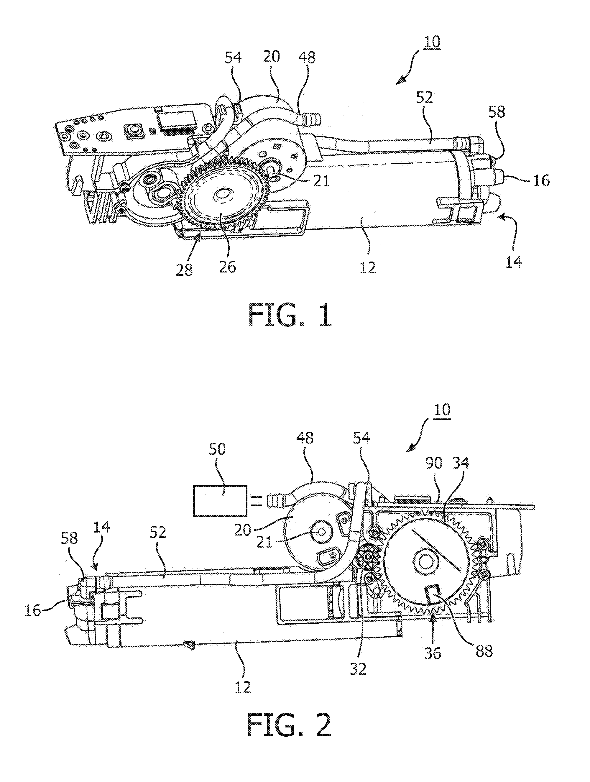
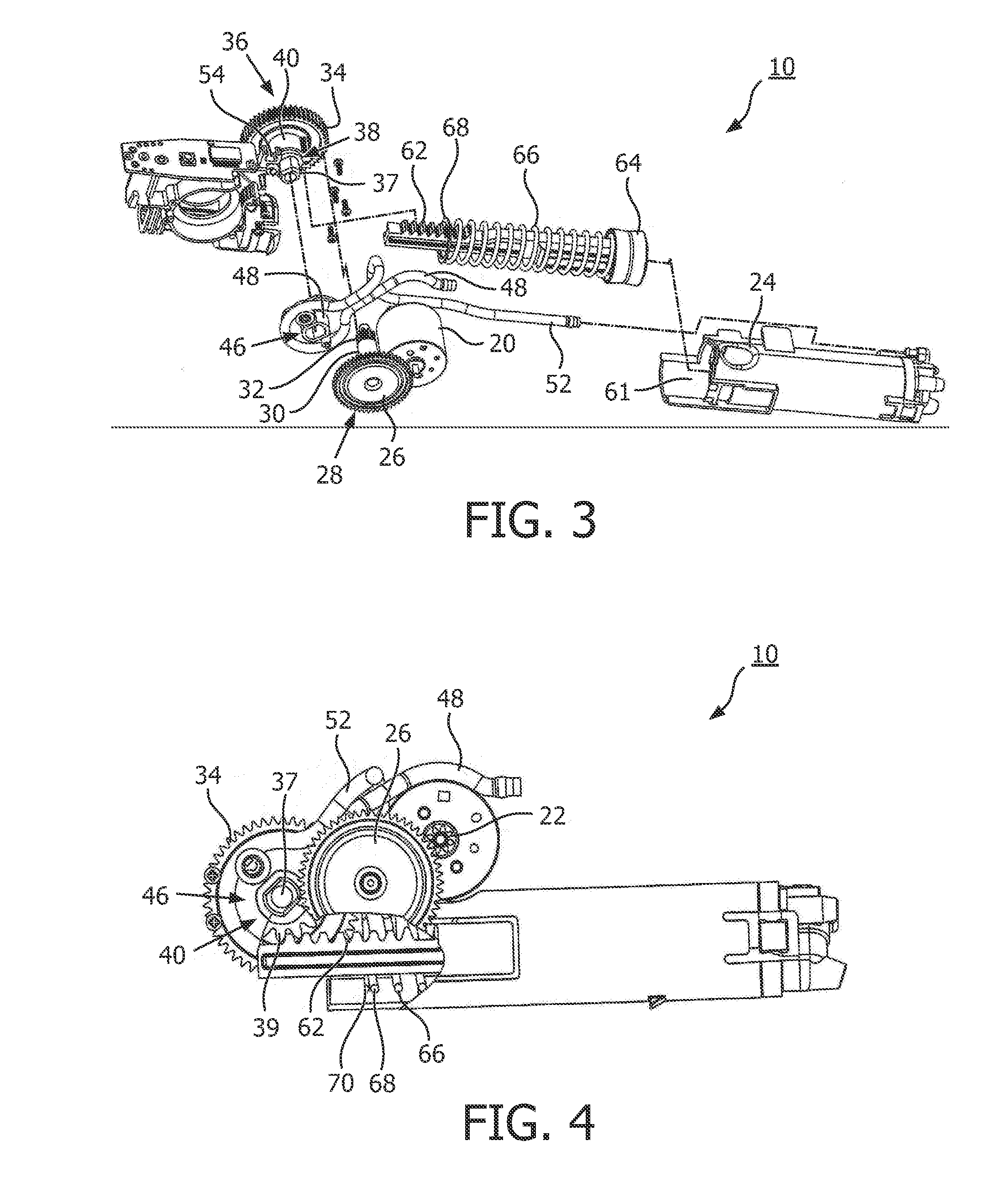
[0015]FIGS. 1-5 show one embodiment of an apparatus, generally at 10, for producing successive bursts of gas and liquid, such as water, which mix to produce a stream of gas and liquid droplets used for cleaning teeth, especially the interproximal areas of the teeth, accomplishing a “flossing” function. The term gas used herein can include air or other gases or mixtures. Apparatus 10 forms the major part of a complete teeth cleaning appliance, the exterior of which is shown in FIG. 6 and described in more detail below.

[0016]Referring now specifically to FIGS. 1 and 2, apparatus 10 includes an gas cylinder 12, which in the embodiment shown is approximately 2.5 inches long with an internal diameter of 0.5-1.0 inches. At a distal end 14 of gas cylinder 12 is a nozzle 16 through which a mix of water or other liquid bursts and fluid, typically gas, exit, in the form of a stream of high velocity liquid droplets. The liquid droplets are directed toward the teeth of a user, particularly the ...


PUM


Abstract

An oral care appliance comprises: a fluid pump assembly (46); a source of liquid (50); and a source of gas (12), wherein the pump is in operative communication with the sources of liquid and gas to produce a series of gas-injected fluid pulses, directed to a nozzle assembly (80) from which the resulting pulses are directed to the teeth. The individual pulses have a pulse width in the range of 0.001-0.5 seconds, a pulse height from 0.1-10 Newtons, and a rise/fall time range of 0.5-250 ms, a repetition rate in the range of 2 Hz to 20 Hz. The gas/liquid mixture range from 40-95% volume to volume, gas to liquid.

Description

TECHNICAL FIELD[0001]This invention relates generally to apparatus for cleaning teeth using a combination of bursts of gas and bursts of fluid to produce a desired gas / fluid mix, and more particularly concerns a single assembly for producing both gas bursts and fluid bursts in coordination, as well as an assembly for producing a jet pattern of gas and fluid in another embodiment.BACKGROUND OF THE INVENTION[0002]In systems which produce teeth cleaning with a combination of bursts of gas and fluid, such as water, it is important that the gas and fluid are mixed in a way to deliver the greatest efficacy of cleaning. In addition it is important to coordinate the timing of these two functions while still being relatively simple in structure and operation, and sufficiently small to fit within a specific device footprint. Use of separate liquid and gas delivery systems typically have some problems with timing, as well as space constraints and the need for dual power sources.SUMMARY OF THE ...

Claims


Application Information

Patent Timeline
Patent Type & Authority Applications(United States)
IPC IPC(8): A61C17/02A61C17/022
CPCA61C17/022A61C17/0202A61C17/02A61C17/0217A61C17/028B05B1/086G06F30/20G06F30/392G06F30/394G06F30/327A61C1/0061
Inventor CHANG, YU-WENGODDARD, GREGORY RUSS
Owner KONINKLJIJKE PHILIPS NV
Why Eureka
Try Eureka