Radiation measuring device

Inactive Publication Date: 2013-06-13
HITACHI LTD
View PDF1 Cites 14 Cited by
  • Summary
  • Abstract
  • Description
  • Claims
  • Application Information

AI Technical Summary

Benefits of technology

[0025]According to the present invention, a radiation measuring device is provided with a simp

Problems solved by technology

However, there are problems such as an increase of noise by adding a circuit, an increase in the number of circuit, a need for adjustment, and an increase in cost, when using analog circuits such as the pole-zero cancellation circuit, the baseline restoration circuit, the pile-up rejection circuit and the pile-up correction circuit.
The impact will be large, especially if the number of detectors is enormous.
In such a case, it is difficult to

Method used


Image

  • Radiation measuring device
  • Radiation measuring device
  • Radiation measuring device

Examples


first embodiment

Circuit Configuration of Radiation Measuring Device

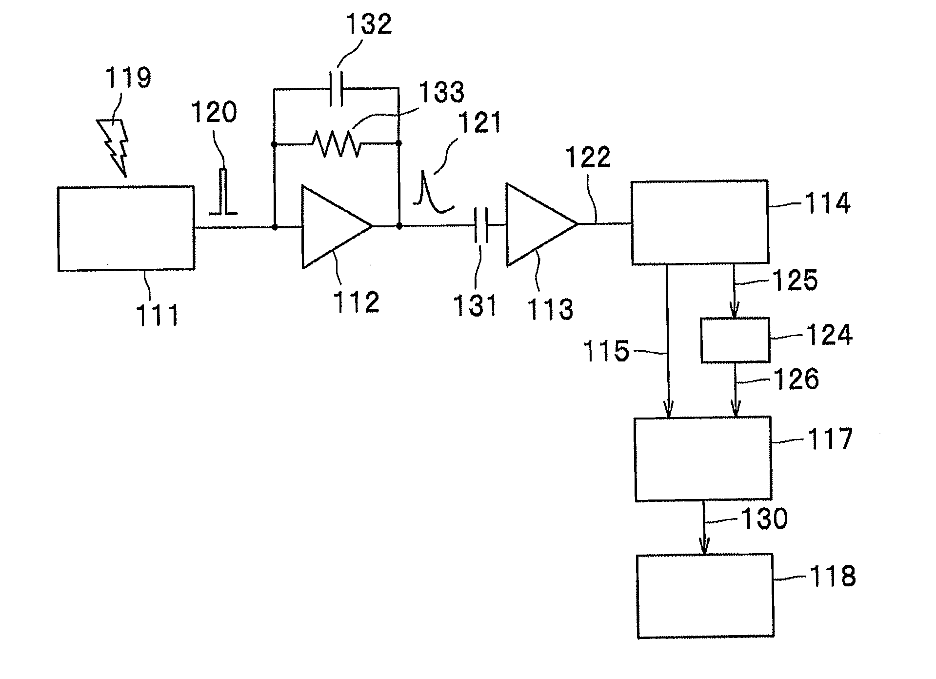
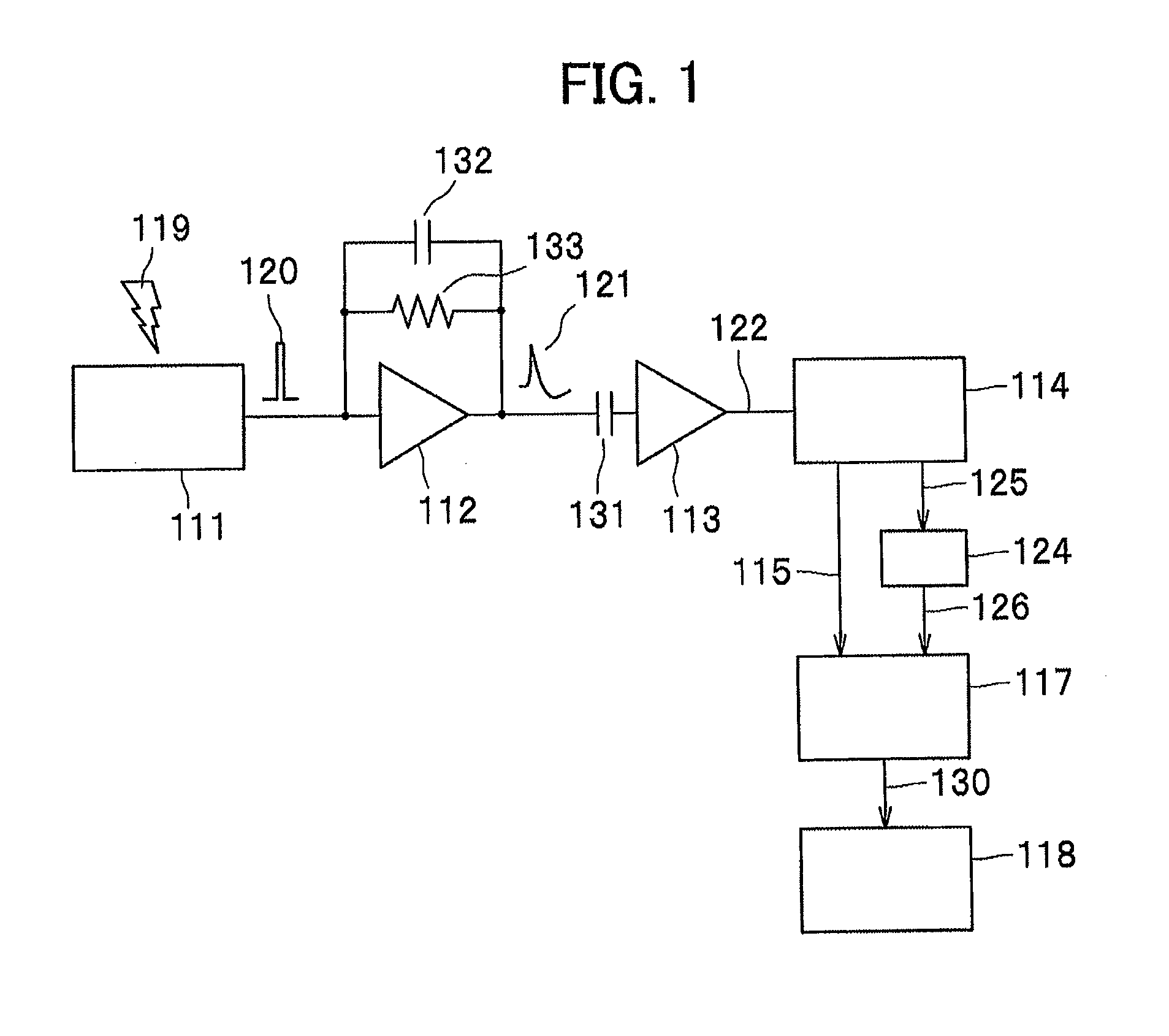
[0035]FIG. 1 is a block diagram showing a circuit configuration (device configuration) of the first embodiment of the present invention.

[0036]In FIG. 1, a detector 111 outputs a charge signal 120 that reflects the energy (energy of one photon), when a gamma ray 119 is input. An output terminal of the detector 111 is connected to the input terminal of a preamplifier 112.

[0037]In order to obtain the energy of the gamma ray 119 accurately, it is necessary to measure the pulse height or the peak value of the pulse signal from the preamplifier 112 accurately.

[0038]The preamplifier 112 is intended to amplify a weak signal from the detector 111 and to ensure the appropriate output impedance.

[0039]The charge signal 120 is inputted to the feedback preamplifier 112, integrated (operation by a capacitor 132) and amplified therein, and a pulse signal 121 is outputted therefrom.

[0040]It should be noted that a feedback resistance 133 and the feed...

second embodiment

[0069]Next, a second embodiment will be described. In this embodiment, an example of a radiation measuring device will be shown that is capable to measure the energy value accurately even when the charge signal 120 comes incident more frequently than the case of the first embodiment.

Circuit Configuration of Radiation Measuring Device

[0070]The circuit configuration (device configuration) of the present embodiment is basically the same configuration as FIG. 1 for the first embodiment. However, the arithmetic unit 117 is required to have a computing unit capable of dealing with a case with a plurality of the charge signals 120 in succession.

Operation of Radiation Measuring Device

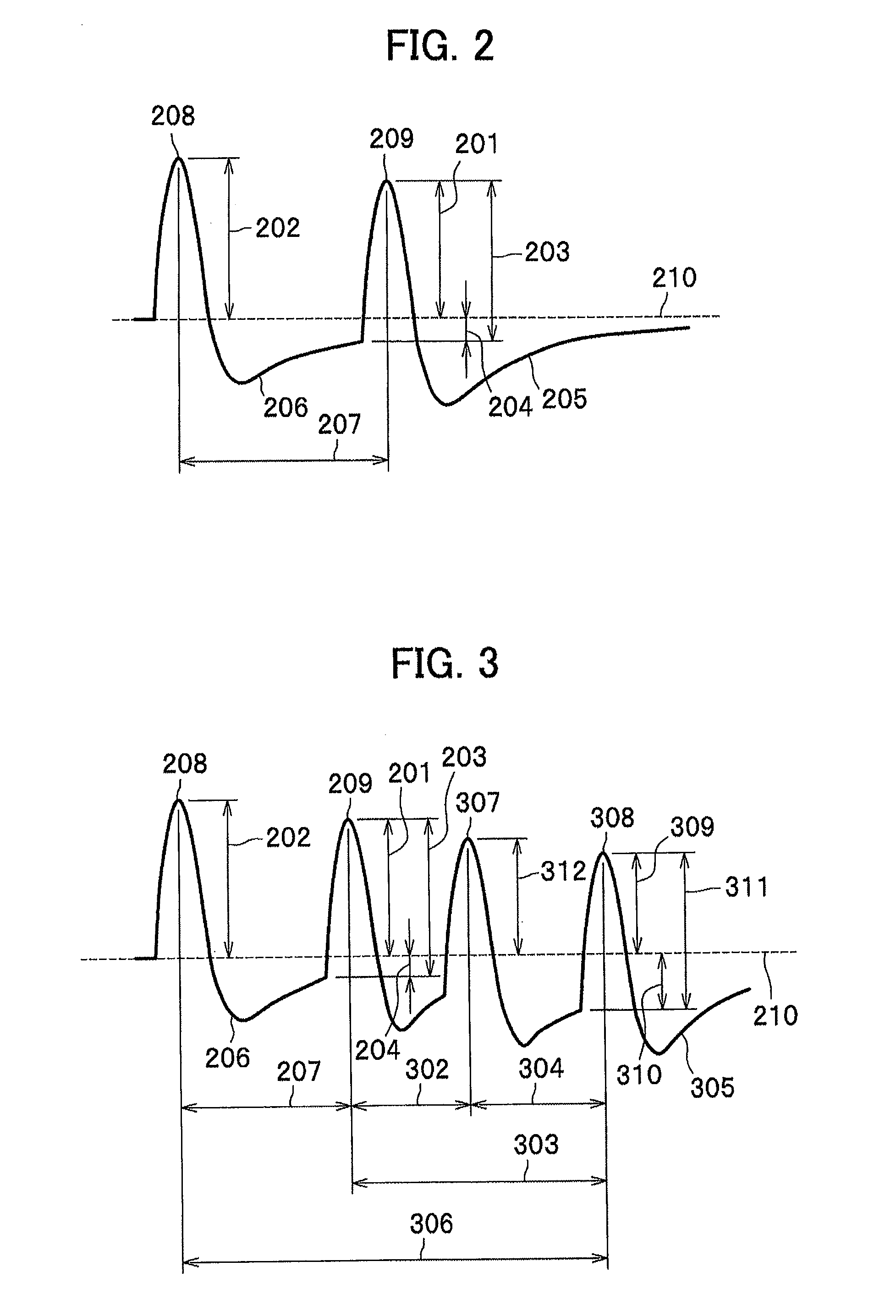
[0071]FIG. 3 is a signal waveform diagram showing an output waveform of the shaping amplifier 113 in a case of four charge signals 120 in succession to the radiation measuring device with the circuit configuration (device configuration) in FIG. 1. In FIG. 3, the parts in common with FIG. 2 are assigned the same...

third embodiment

[0082]Next, a third embodiment will be described. In this embodiment, an example will be shown to implement the present invention corresponding to a case where the next pulse is generated in shorter time than the case of the first embodiment.

Circuit Configuration of Radiation Measuring Device

[0083]The circuit configuration (device configuration) of the present embodiment is basically same as FIG. 1 for the first embodiment. However, the arithmetic unit 117 is required to have a computing unit capable of dealing with a case when the next pulse is generated in shorter time than the case of the first embodiment.

Operation of Radiation Measuring Device

[0084]FIG. 4 is a diagram showing the output waveform of the shaping amplifier 113 in a case where a next charge signal 120 comes incident to the radiation measuring device with the device configuration in FIG. 1 immediately after the charge signal 120 reaches a peak. It should be noted that FIG. 4 shows a state in which a second pulse 409 ...


PUM


Abstract

A radiation measuring device includes: a detector that detects radiation; a preamplifier that amplifies a signal outputted from the detector; a shaping amplifier that shapes the waveform of the signal outputted from the preamplifier; an A/D converter that converts the analog signal output from the shaping amplifier to a digital signal; and a digital data processing unit that calculates digital signal output from the A/D converter, wherein energy information of the radiation inputted to the detector is obtained from a pulse height of the pulse signal processed by the preamplifier and the shaping amplifier, and the pulse height of the current pulse is corrected in the digital data processing unit by performing an arithmetic operation using the pulse height information of the current pulse digitalized by the A/D converter, the generation time information of the preceding pulse, and the pulse height information of the preceding pulse.

Description

TECHNICAL FIELD[0001]The present invention relates to a radiation measuring device.BACKGROUND OF INVENTION[0002]In the field of radiation measurement devices, one of the important indicators of the device performance is an ability to measure photon energies of gamma rays, X-rays or the like with high accuracy. As one photon of coming incident generates an amount of electric charge or light emission roughly in proportion to the photon energy, a semiconductor detector or a scintillation detector measures the photon energy by measuring the generated amount, respectively.[0003]In the measurement, the semiconductor detector generates an electric charge, which is outputted as an electrical signal as it is. On the other hand, the scintillator generates light emission, which is converted to an electric signal by a photomultiplier tube or the like then outputted as a signal. In general, as the output signals from these detectors are weak, the detector output is input to and amplified by the ...

Claims


Application Information

Patent Timeline
IPC IPC(8): G01T1/17
CPCG01T1/171G01T1/17
Inventor SEINO, TOMOYUKIUENO, YUICHIROISHITSU, TAKAFUMI
Owner HITACHI LTD
Why Eureka
Try Eureka