Radiographic apparatus for detecting photons with offset correction

a radiation apparatus and offset correction technology, applied in the direction of optical radiation measurement, material analysis using wave/particle radiation, instruments, etc., can solve the problems of reducing the quality of generated detection values, corrupted signal pulse distribution, etc., to reduce the general possibility of disturbance in the determination and improve the reliability of the offset determination

Active Publication Date: 2014-11-06
KONINKLIJKE PHILIPS ELECTRONICS NV
View PDF1 Cites 14 Cited by
  • Summary
  • Abstract
  • Description
  • Claims
  • Application Information

AI Technical Summary

Benefits of technology

[0004]It is an object of the present invention to provide a detection apparatus, a detection method and a detection computer program for detecting photons, which allow reliably determining the offset. It is a further object of the present invention to provide an imaging apparatus, which comprises the detection apparatus, and a corresponding imaging method and imaging computer program for imaging the object.

Problems solved by technology

This offset may lead to a corrupted distribution of the signal pulses among the energy bins and, thus, to a reduced quality of the generated detection values.

Method used


Image

  • Radiographic apparatus for detecting photons with offset correction
  • Radiographic apparatus for detecting photons with offset correction
  • Radiographic apparatus for detecting photons with offset correction

Examples


Embodiment Construction

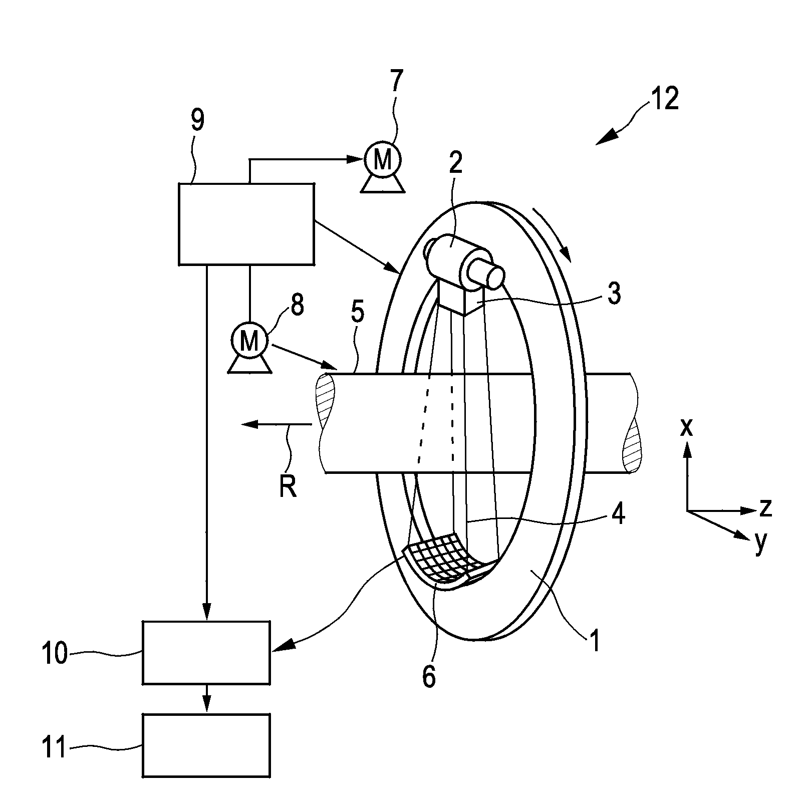
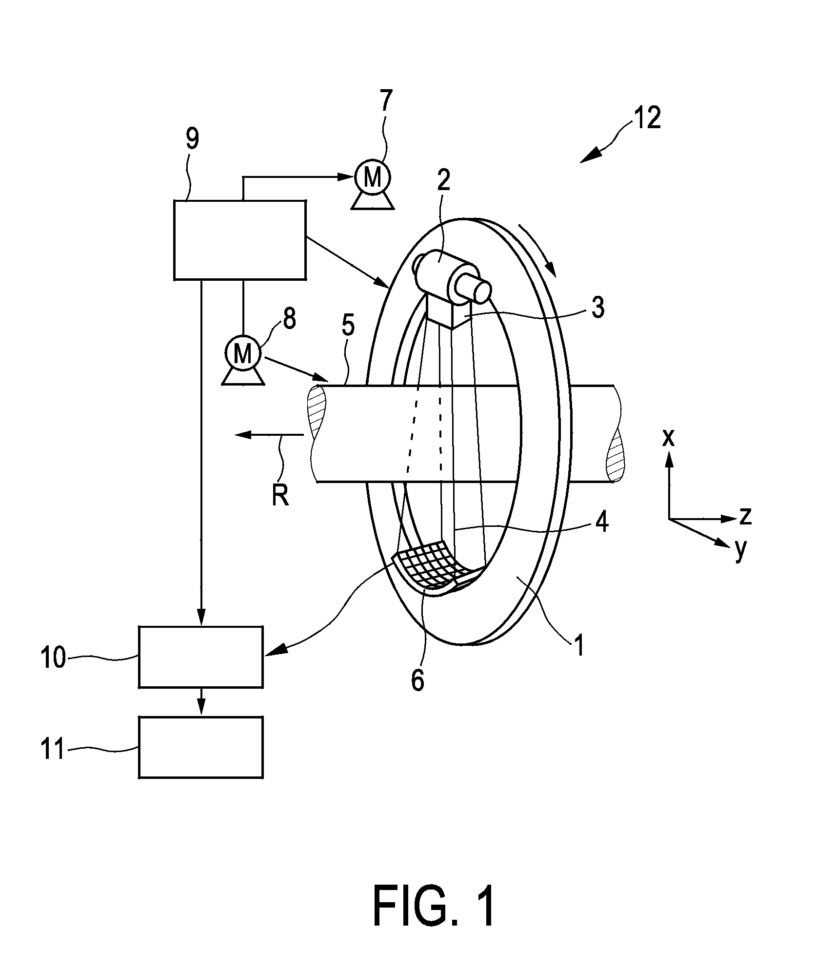
[0053]FIG. 1 shows schematically and exemplarily an imaging apparatus for imaging an object being a computed tomography apparatus 12. The computed tomography apparatus 12 includes a gantry 1, which is capable of rotation about a rotational axis R, which extends parallel to a z direction. A photon source 2, which is, in this embodiment, a polychromatic x-ray tube, is mounted on the gantry 1. The photon source 2 is provided with a collimator 3, which forms, in this embodiment, a conical radiation beam 4 from the photons generated by the photon source 2. The photons traverse an object such as a patient in an examination zone 5, which is, in this embodiment, cylindrical. After having traversed the examination zone 5, the radiation beam 4 is incident on a detection apparatus 6, which comprises a two-dimensional detection surface. The detection apparatus 6 is mounted on the gantry 1.

[0054]The computed tomography apparatus 12 comprises two motors 7, 8. The gantry 1 is driven at a preferabl...


PUM

PropertyMeasurementUnit
energyaaaaaaaaaa
heightaaaaaaaaaa
heightsaaaaaaaaaa

Abstract

The invention relates to a detection apparatus for detecting photons, such as used in radiographic imaging systems. A detection unit (14) generates detection signal pulses having a detection signal pulse height being indicative of the energy of the detected photons (13), wherein a detection values generation unit (16) generates energy-resolved detection values depending on the detection signal pulses. A signal pulse generation unit (15) generates artificial signal pulses having a predefined artificial signal pulse height and a predefined generated rate. The detection values generation unit (16) determines an observed rate being the rate of the artificial signal pulses having an artificial signal pulse height being larger than a predefined threshold as observed by the detection values generation unit (16) and determines an offset of the detection signal pulses depending on the determined observed rate. This allows reliably determining the offset of the detection signal pulses, such as produced by dark current drift in radiographic detection devices, which can be used for correcting the finally generated detection values.

Description

FIELD OF THE INVENTION[0001]The invention relates to a detection apparatus, a detection method and a detection computer program for detecting photons. The invention relates further to an imaging apparatus, an imaging method and an imaging computer program for imaging an object.BACKGROUND OF THE INVENTION[0002]The article “Medipix2: A 64-k pixel readout chip with 55-μm square elements working in single photon counting mode” by X. Llopart et al., IEEE Transactions on Nuclear Science, volume 49, issue 5, pages 2279 to 2283, October 2002 discloses a photon counting detector, which generates detection values depending on detected photons. In particular, a direct conversion material is used for transforming photons into signal pulses, wherein each signal pulse corresponds to a single photon and wherein the signal pulse height of the respective signal pulse is indicative of the energy of the respective photon. The signal pulses are distributed among several energy bins, wherein for each en...

Claims


Application Information

Patent Timeline
Patent Type & Authority Applications(United States)
IPC IPC(8): G01T1/17G01N23/04
CPCG01N23/04G01T1/17G01N23/046G01N2223/419
Inventor PROKSA, ROLAND
Owner KONINKLIJKE PHILIPS ELECTRONICS NV
Why Eureka
Try Eureka