Stereo Audio Encoder and Decoder

a decoder and stereo coding technology, applied in the field of stereo audio coding, can solve problems such as the difficulty of getting the best out of low bandwidth waveform based stereo coding in the mdct domain

Active Publication Date: 2016-01-28
DOLBY INT AB
View PDF0 Cites 14 Cited by
  • Summary
  • Abstract
  • Description
  • Claims
  • Application Information

AI Technical Summary

Problems solved by technology

The drawback with the solution is that it may be difficult to get the best out of the low bandwidth waveform based stereo codin

Method used


Image

  • Stereo Audio Encoder and Decoder
  • Stereo Audio Encoder and Decoder
  • Stereo Audio Encoder and Decoder

Examples


Embodiment Construction
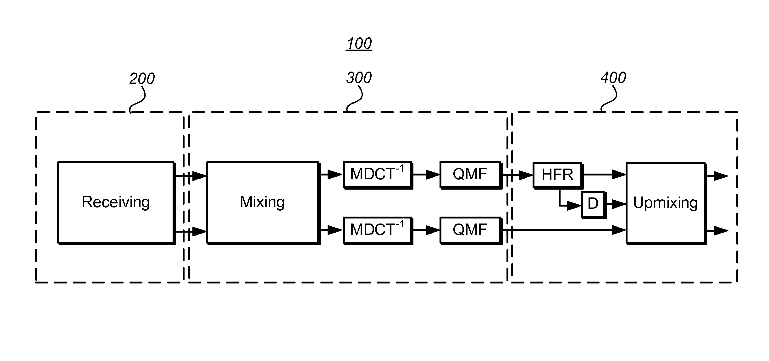
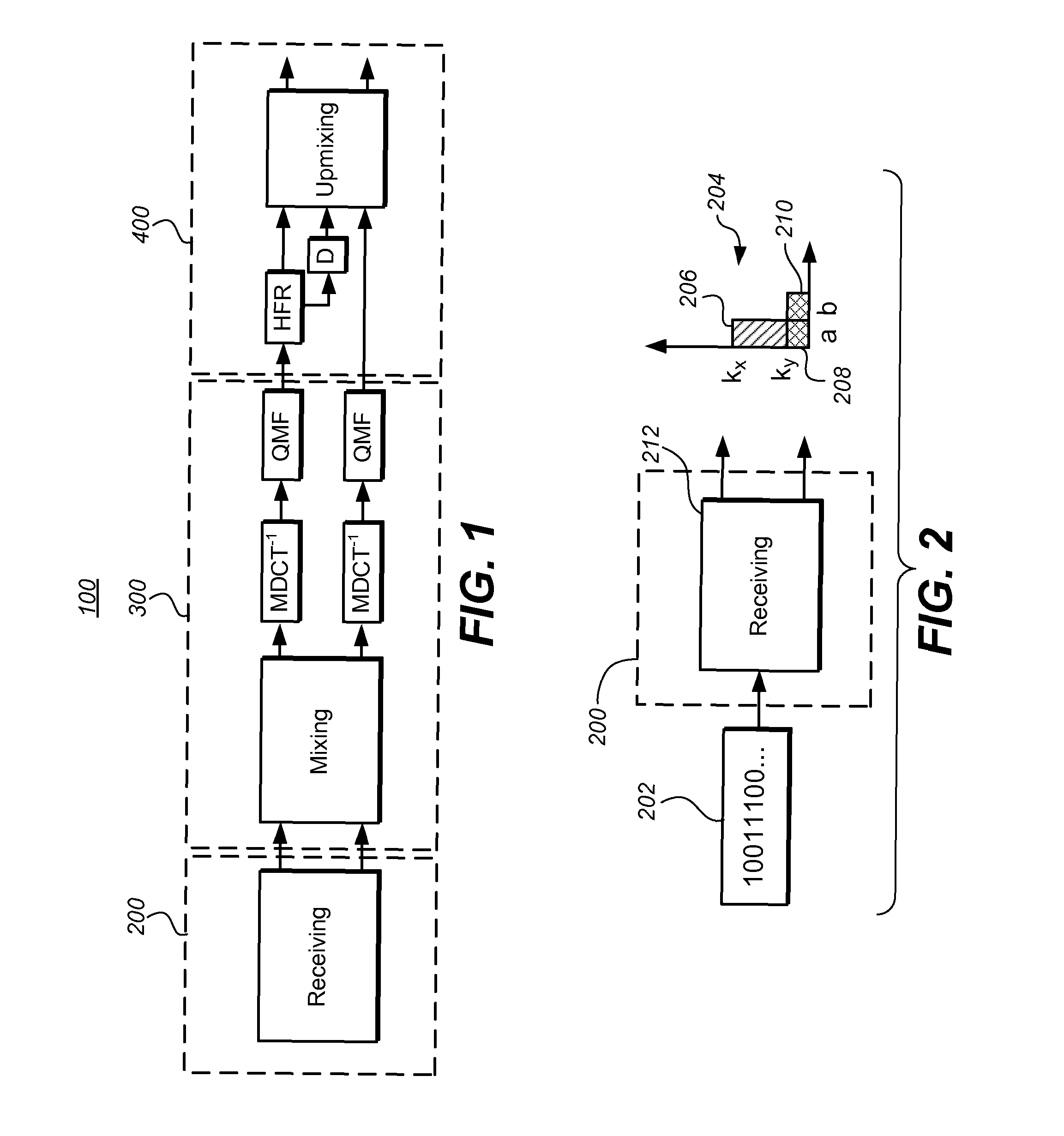
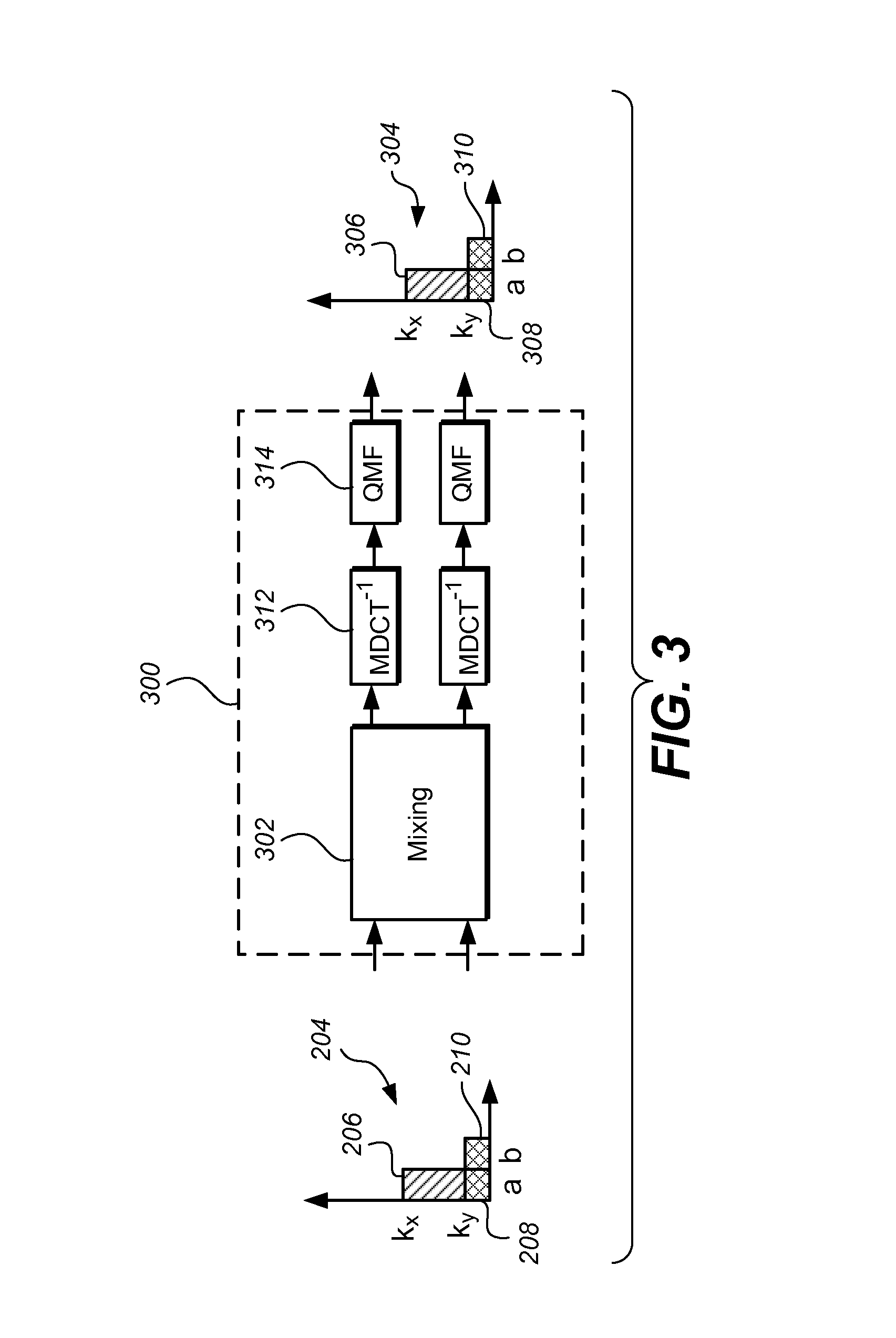
I. Overview—Decoder

[0013]As used herein, left-right coding or encoding means that the left (L) and right (R) stereo signals are coded without performing any transformation between the signals.

[0014]As used herein, sum-and difference coding or encoding means that the sum M of the left and right stereo signals are coded as one signal (sum) and the difference S between the left and right stereo signal are coded as one signal (difference). The sum-and-difference coding may also be called mid-side coding. The relation between the left-right form and the sum-difference form is thus M=L+R and S=L−R. It may be noted that different normalizations or scaling are possible when transforming left and right stereo signals into the sum-and difference form and vice versa, as long as the transforming in both direction matches. In this disclosure, M=L+R and S=L−R is primarily used, but a system using a different scaling, e.g. M=(L+R) / 2 and S=(L−R) / 2 works equally well.

[0015]As used herein, downmix-co...


PUM


Abstract

The present disclosure provides methods, devices and computer program products for encoding and decoding a stereo audio signal based on an input signal. According to the disclosure, a hybrid approach of using both parametric stereo coding and a discrete representation of the stereo audio signal is used which may improve the quality of the encoded and decoded audio for certain bitrates.

Description

TECHNICAL FIELD OF THE INVENTION [0001]The disclosure herein generally relates to stereo audio coding. In particular it relates to a decoder and an encoder for hybrid coding comprising a downmix and discrete stereo coding.BACKGROUND OF THE INVENTION[0002]In conventional stereo audio coding, possible coding schemes include parametric stereo coding techniques which are used in low bitrate applications. At intermediate rates, Left / Right (L / R) or Mid / Side (M / S) waveform stereo coding is often used. The existing distribution formats and the associated coding techniques may be improved from the point of view of their bandwidth efficiency, especially in applications with a bitrate in between the low bitrate and the intermediate bitrate.[0003]An attempt to improve the efficiency of the audio distribution in a stereo audio system is made in the Unified Speech and Audio Coding (USAC) standard. The USAC standard introduces a low bandwidth waveform-coding based stereo coding in combination with...

Claims


Application Information

Patent Timeline
IPC IPC(8): G10L19/008G10L19/02G10L25/06H04S1/00
CPCG10L19/008H04S1/007H04S2420/03G10L19/02H04S2400/03G10L25/06G10L19/167G10L19/0204G10L19/0212G10L19/06G10L19/265
Inventor PURNHAGEN, HEIKOKJOERLING, KRISTOFER
Owner DOLBY INT AB
Why Eureka
Try Eureka