

Bundled wire component separator and contact assembly
- Summary
- Abstract
- Description
- Claims
- Application Information
AI Technical Summary
Benefits of technology
Problems solved by technology
Method used
Image

Examples
exemplary embodiment 150
[0056]A similar exemplary embodiment 150 of the invented contact assembly is shown in connection with FIGS. 15-16. Here, the contact assembly 150 is provided with a snap-on type strain relief component 152, which is placed laterally across the back surface 124 of the electrical device 102 to secure one or more bundled wires and provide strain relief to the component wires when affixed to the contact areas by set screws 118 or other such mechanical fasteners as described above. As provided in the previously described embodiments, the strain relief component 152 defines a bundled wire inlet 6, and in this embodiment snap fits into place with gripping arms 154 extending along the sides of the electrical device 102 wherein grooves 156 are used to hold the strain relief component 152 securely in place. This optional configuration is preferred in part because the strain relief component 152 is removable, providing ready access when installing the component wires, and also because it may b...
exemplary embodiment 221
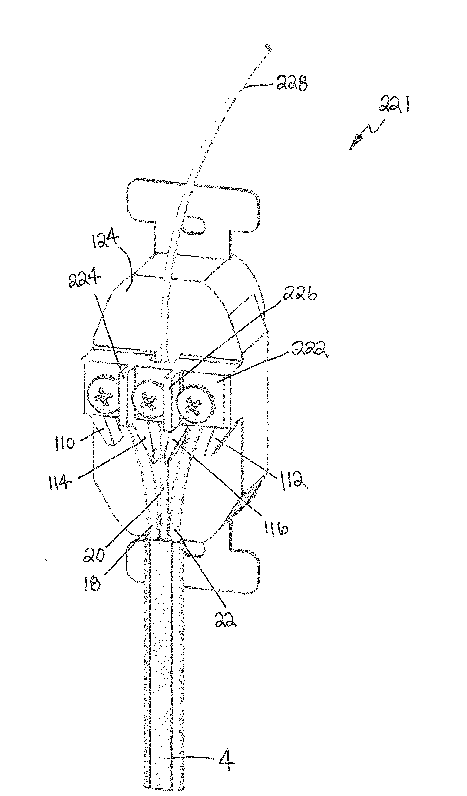
[0065]FIGS. 24-32 illustrate a further exemplary embodiment 221 of the invented contact assembly. Here the contact assembly 221 further includes a bridge 222, which may be integrally formed with the electrical device or housing (e.g., outlet 102 as shown or housing 162 as shown in connection with FIGS. 17-19, for instance), or may be otherwise attached thereto. The bridge 222 may span the back surface 124 of the device 102 and may receive the component wires 18, 20 and 22 of the bundled wire 4, and assist in affixing the component wires 18, 20 and 22 therein. The bundled wire 4 may be inserted from the bottom of the contact assembly 221 and the component wires 18, 20 and 22 may be separated by the side walls 110 and 112 and separating fins 114 and 116 into the component wire channels 104, 106, and 108, respectively. The component wires 18, 20 and 22 may be inserted until the ends of at least component wires 18 and 22 contact a rear surface 223 of the bridge 222. In exemplary embodim...
PUM
 Abstract
Description
Claims
Application Information