Wireless charging stand

a charging stand and wireless technology, applied in the direction of mechanical equipment, machine supports, transportation and packaging, etc., can solve the problem of limited discharg

Active Publication Date: 2016-02-04
WONG CHIH JUH
View PDF2 Cites 32 Cited by
  • Summary
  • Abstract
  • Description
  • Claims
  • Application Information

AI Technical Summary

Problems solved by technology

However, the inducing current influence a power charge of the handheld electronic device based on magnetic flux of the second coil / per unit time, and the magnetic flux is limited by a distance and an angle between the wireless charging transmitter and the wireless charging receiver.

Method used


Image

  • Wireless charging stand
  • Wireless charging stand
  • Wireless charging stand

Examples


first embodiment

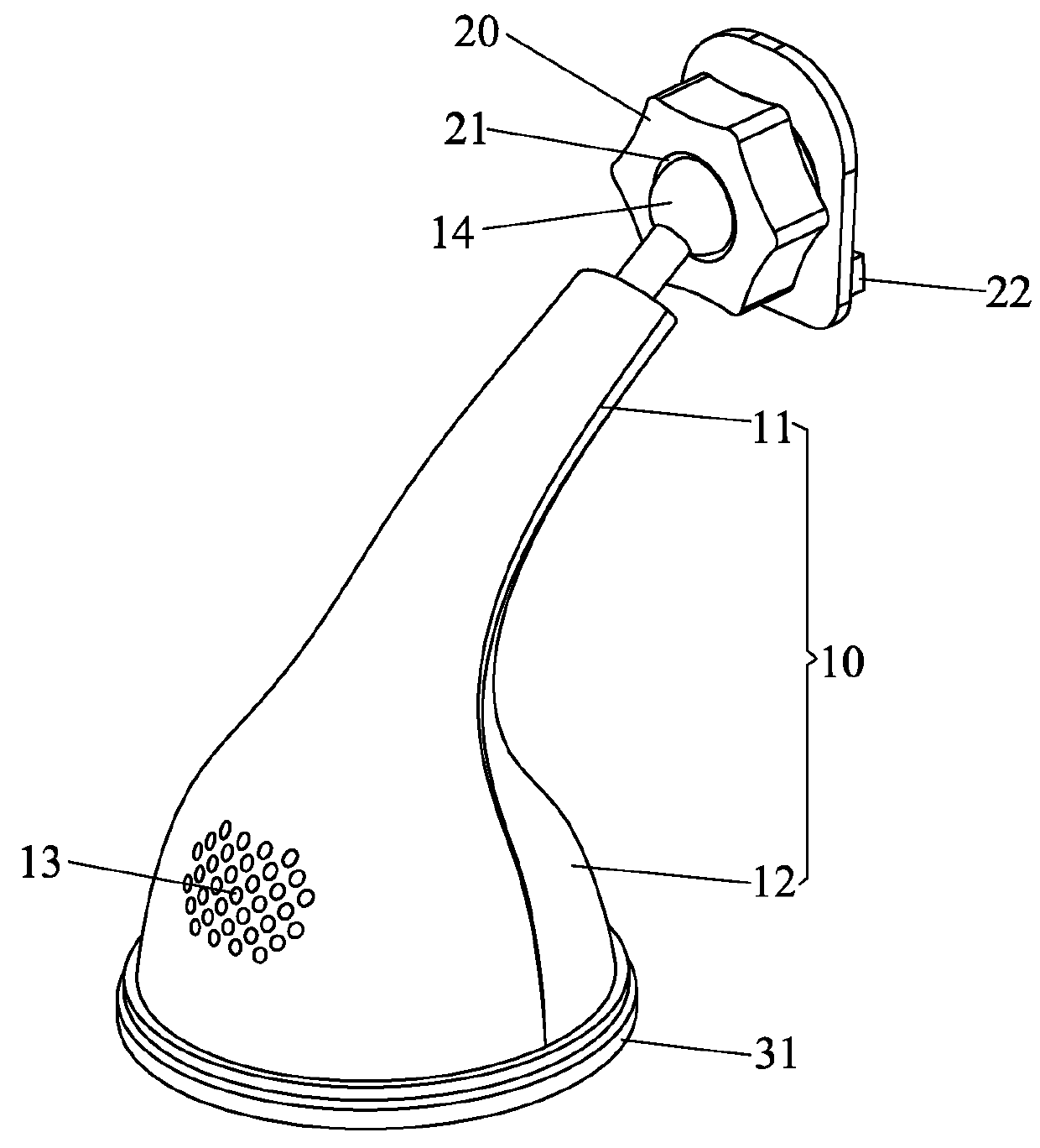
[0024]FIGS. 1 and 2, a wireless charging stand 100 according to the present invention comprises: a body 10, a rotary head 20, and a bluetooth mechanism (not shown) accommodated in the body 10. The wireless charging stand 100 also comprises a wireless charging transmitter 40 (as shown in FIG. 8). The body 10 includes an upper segment 11 axially connected with the rotary head 20 which universally rotates on the upper segment 11 and couples with and removes from a handheld electronic device. The wireless charging transmitter 40 is accommodated in or on the body 10 to wirelessly charge power to the handheld electronic device, wherein the bluetooth mechanism includes a bluetooth module, a speaker, and a first power component for supplying the power. The speaker and the first power component are electrically connected with the bluetooth module, and the bluetooth module receives audio information of the handheld electronic device and plays the audio information by ways of the speaker. The ...

second embodiment

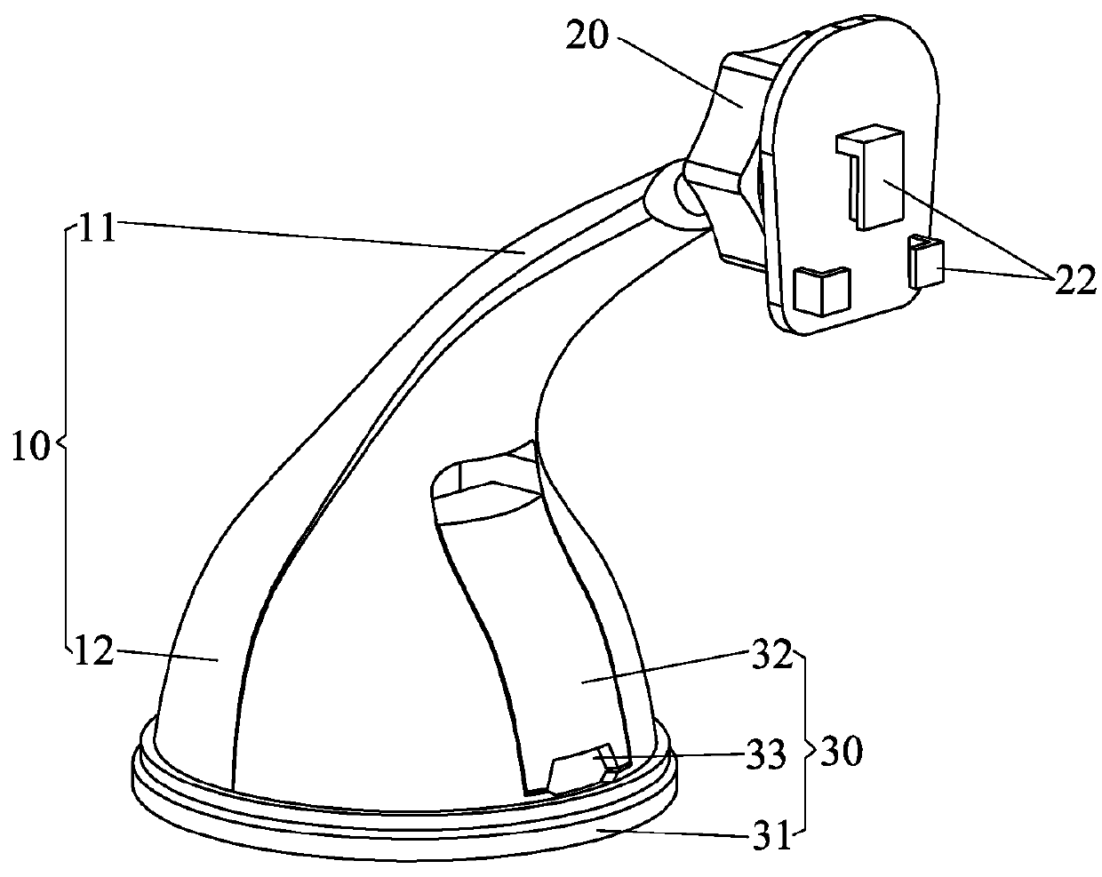
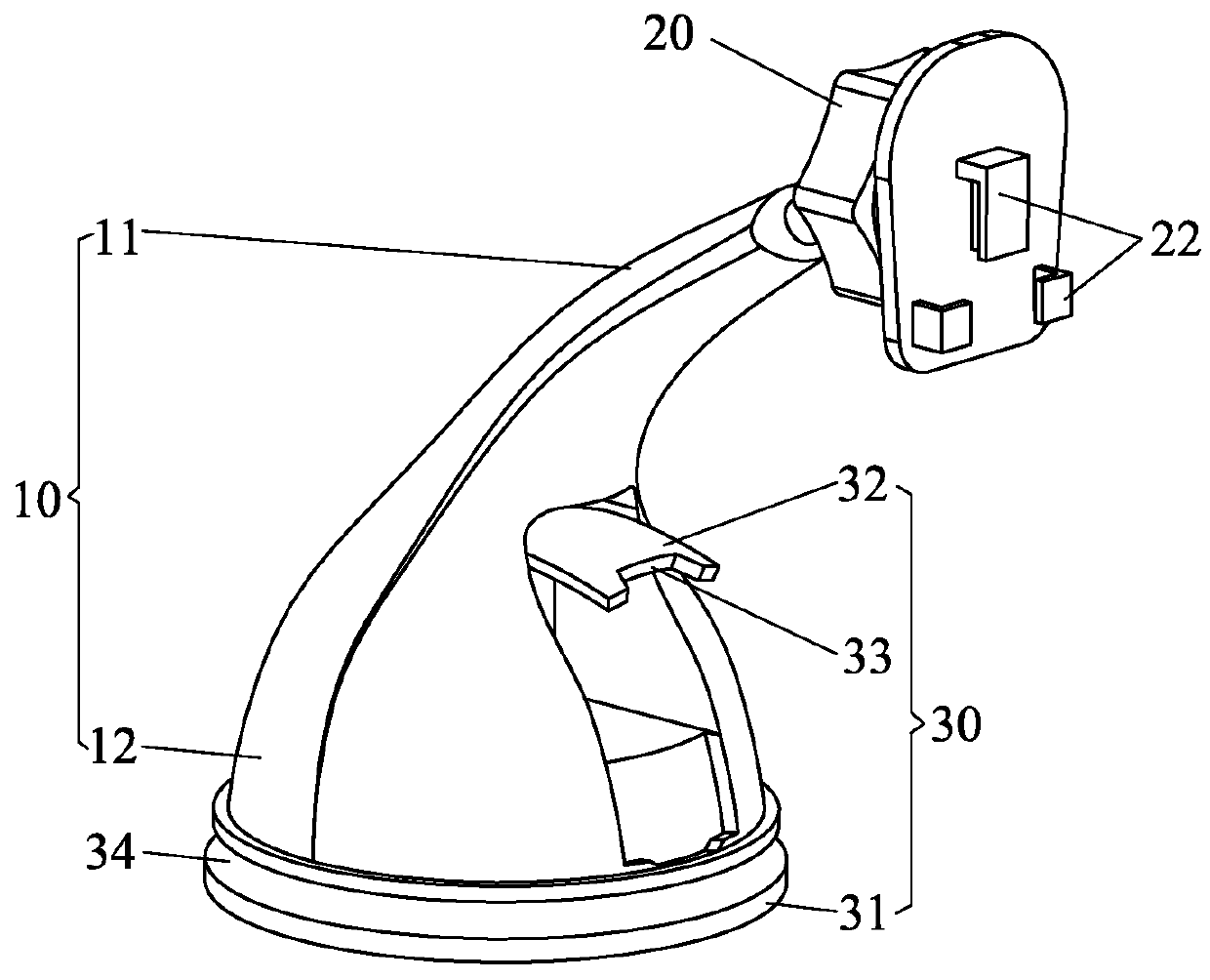
[0036]With reference to FIG. 7, a flexible puller 32 of the second embodiment has an operating tab 35 extending outwardly from a bottom end thereof so that when the user's finger pulls the operating tab 35 outwardly, the bottom end of the flexible puller 32 rotates outwardly and the upper end of the flexible puller 32 inwardly rotates to the body 10, such that the upper end of the flexible puller 32 pushes the sucker to move downwardly, and the gap forms between the sucker 31 and the body 10, thus removing the body 10 from the support surface easily.

[0037]Accordingly, the handheld electronic device is universally rotated on the wireless charging stand 100 randomly and stably.

[0038]As shown in FIGS. 9 and 10, the protective case 60 of a mobile phone is connected with the wireless charging stand 100, wherein the protective case 60 has at least one trough 61 for cooperating with the at least one locking protrusion 22, such that the mobile phone is connected with or disconnected from th...


PUM


Abstract

A wireless charging stand is used to position a handheld electronic device and contains: a body, a wireless charging transmitter, a rotary head, a body, and a bluetooth mechanism accommodated in the body. The body includes an upper segment axially connected with the rotary head which universally rotates on the upper segment and couples with and removes from the handheld electronic device. The wireless charging transmitter is accommodated in or on the body to wirelessly charge power to the handheld electronic device. The bluetooth mechanism includes a bluetooth module, a speaker, and a first power component for supplying the power. The speaker and the first power component are electrically connected with the bluetooth module, the bluetooth module receives audio information of the handheld electronic device and plays the audio information by ways of the speaker, and the first power component is also electrically connected with the wireless charging transmitter.

Description

FIELD OF THE INVENTION[0001]The present invention relates to a wireless charging stand which has bluetooth and wireless charging functions.BACKGROUND OF THE INVENTION[0002]A handheld electronic device, such as a mobile phone, is manually held by a user and is charged power by using a charger, a cable or a mobile power, so the handheld electronic device is charged the power within a limited range of a power source.[0003]To overcome above-mentioned problem, a wireless charger is developed and contains a wireless charging transmitter and a wireless charging receiver, wherein the wireless charging transmitter has a first circuit board with a first coil, and the wireless charging receiver has a second circuit board with a second coil, such that a magnetic field forms on the first coil and acts on the second coil, thus resulting electromagnetic induction. Thereafter, the second coil generates inducing current to charge the power to the handheld electronic device.[0004]However, the inducin...

Claims


Application Information

Patent Timeline
Patent Type & Authority Applications(United States)
IPC IPC(8): H04B1/3883H02J7/00H02J7/02
CPCH04B1/3883H02J7/0044F16M11/041H04M1/04F16M13/00H02J7/025F16M11/14F16M13/022F16B47/006H02J50/10
Inventor WONG, CHIH-JUH
Owner WONG CHIH JUH
Why Eureka
Try Eureka