Pneumatic tire
a pneumatic tire and tread technology, applied in the field of pneumatic tires, can solve the problems of reduced rigidity of the tread portion and deterioration of steering stability, and achieve the effects of preventing the rigidity of the outboard middle land portion from decreasing, improving steering stability, and reducing rigidity differences
Active Publication Date: 2016-02-11
SUMITOMO RUBBER IND LTD
View PDF7 Cites 14 Cited by
- Summary
- Abstract
- Description
- Claims
- Application Information
AI Technical Summary
Benefits of technology
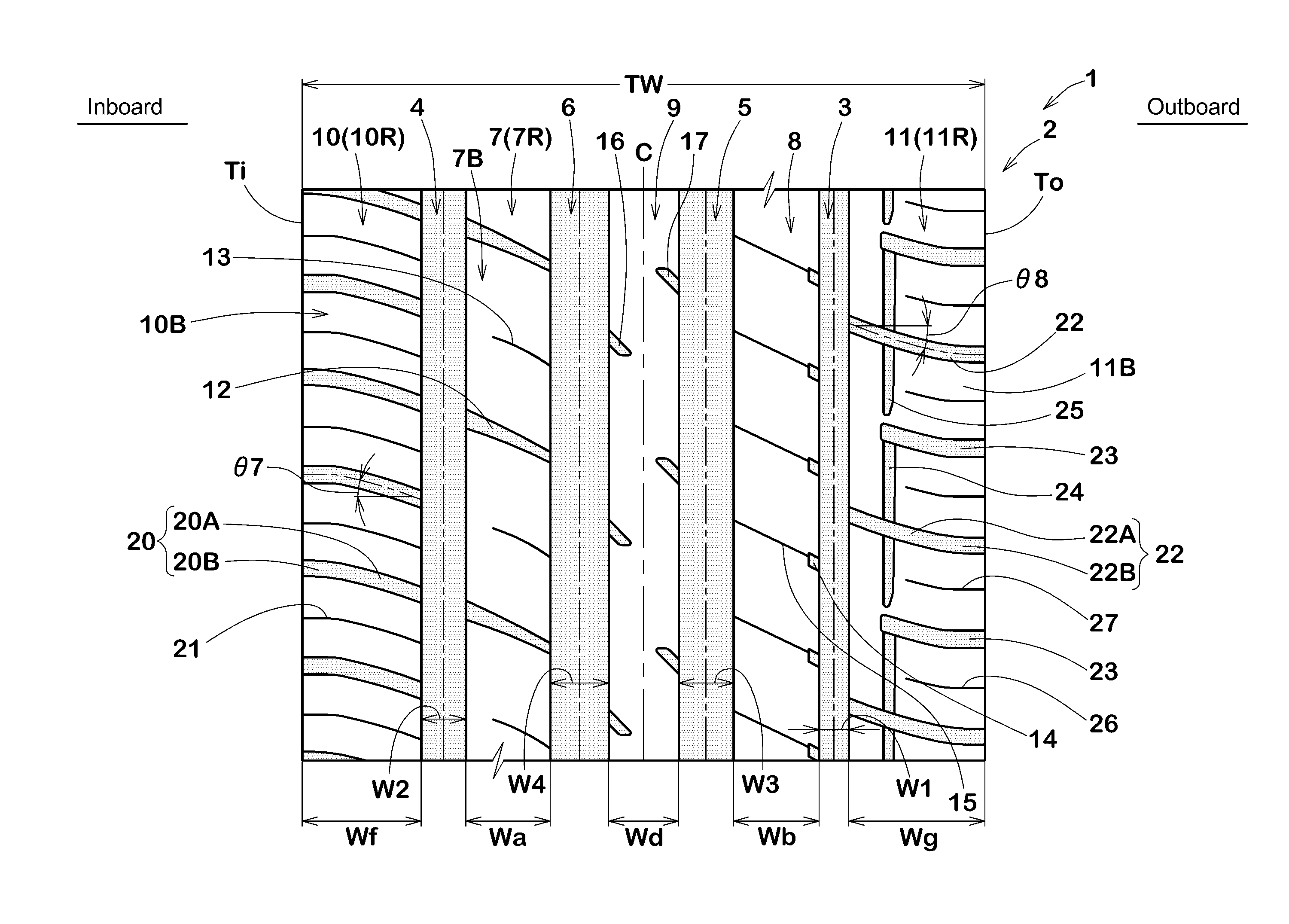
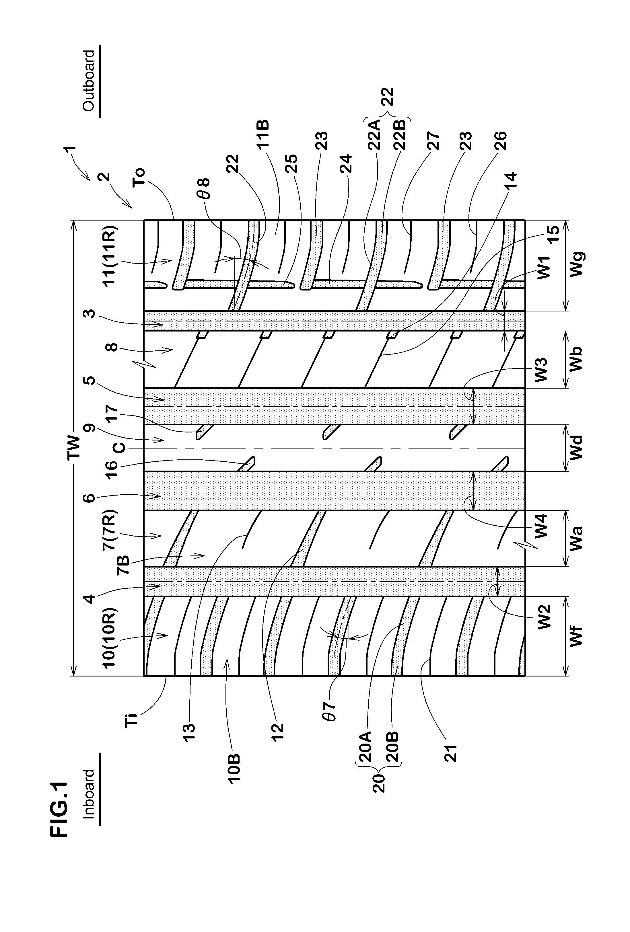
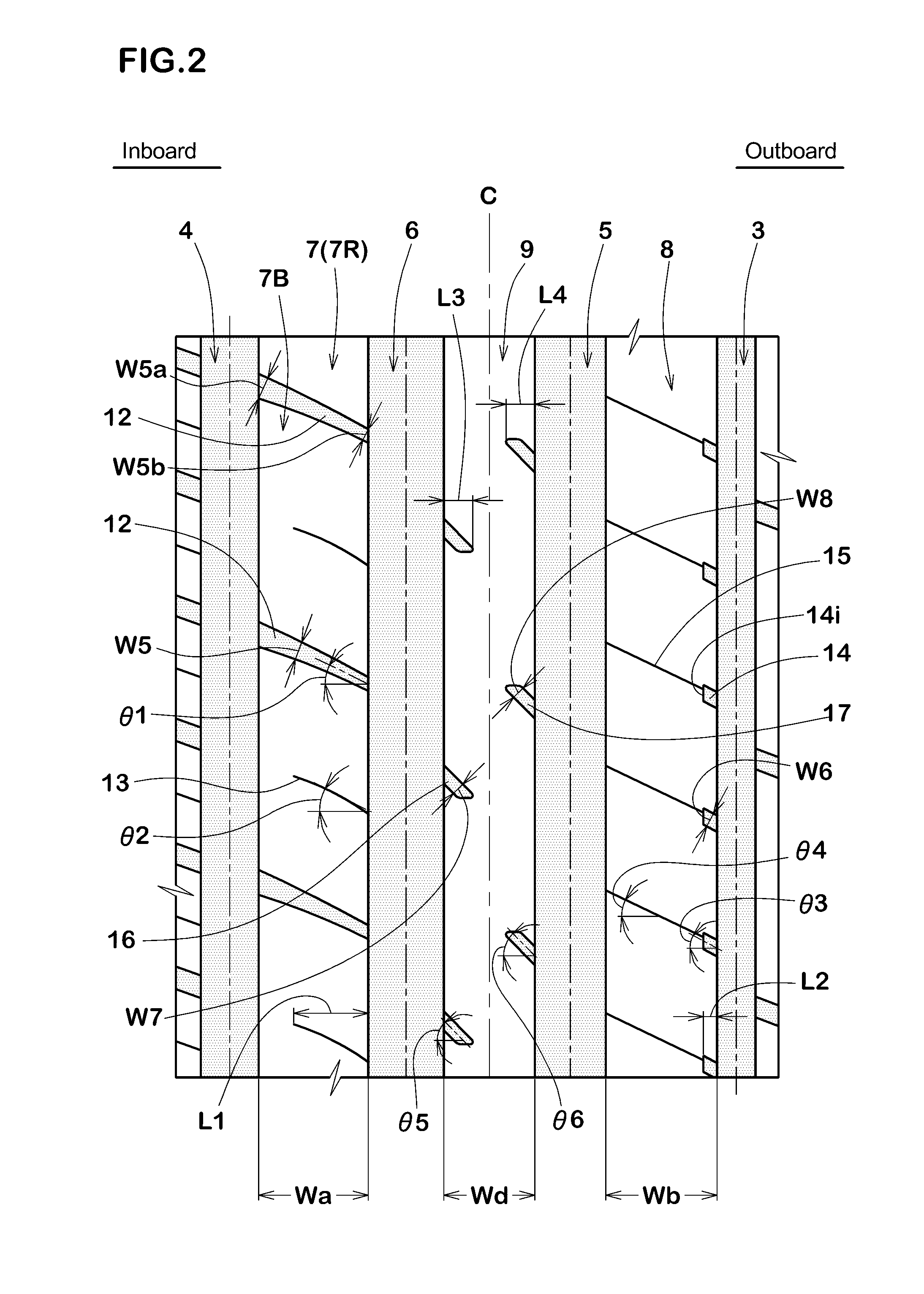
[0013]The inboard middle axial grooves ensure axial rigidity of the inboard middle land portion, and can lead the water therein toward the main grooves by utilizing tire rotations. Accordingly, the wet performance and the steering stability are improved in a well balanced manner.
[0014]The outboard middle semi-blind grooves and the outboard middle sipes prevent the rigidity of the outboard middle land portion from decreasing. Therefore, the difference in rigidity is decreased between the outboard middle land portion subjected to a large lateral force during cornering and the inboard middle land portion provided with the inboard middle axial grooves, and both clockwise vehicle turning and counter-clockwise vehicle turning can be made smoothly to further improve the steering stability. The outboard middle Sipes improve the wet performance by their water-absorbing property and edge effect.
[0015]The center land portion is provided with the inboard crown semi-blind grooves
Problems solved by technology
In such pneumatic tire, however, due to the grooves having a large groove volume, the rig
Method used
View moreImage
Smart ImageViewing Examples
Examples
 PUM
 Abstract
A pneumatic tire has a tread pattern capable of improving wet performance and steering stability in a well balanced manner. An inboard middle land portion is provided with inboard middle axial grooves connecting between an inboard shoulder main groove and an inboard crown main groove and inclined at 20 to 30 degrees. An outboard middle land portion is provided with outboard middle semi-blind grooves extending axially inwardly from a outboard shoulder main groove, and outboard middle sipes extending from the axially inner ends of the outboard middle semi-blind grooves to the outboard crown main groove. The outboard middle semi-blind grooves and the outboard middle sipes are inclined at 20 to 30 degrees. A center land portion is provided with inboard crown semi-blind grooves extending from the inboard crown main groove, and outboard crown semi-blind grooves extending from the outboard crown main groove.
Description
BACKGROUND OF THE INVENTION[0001]The present invention relates to a pneumatic tire, more particularly to a tread pattern capable of improving wet performance and steering stability in a well balanced manner.[0002]Pneumatic tires are required to exert excellent wet performance and steering stability. In order to improve wet performance, the tread portion of a pneumatic tire is usually provided with circumferential grooves and / or axial grooves having a large groove volume.[0003]In such pneumatic tire, however, due to the grooves having a large groove volume, the rigidity of the tread portion is decreased, and the steering stability tends to deteriorate.SUMMARY OF THE INVENTION[0004]It is therefore, an object of the present invention to provide a pneumatic tire, in which wet performance and steering stability are improved in a well balanced manner.[0005]The pneumatic tire according to the present invention is an asymmetrical tire whose tread pattern is asymmetric about the tire equator...
Claims
Login to View More Application Information
Patent Timeline
 IPC IPC(8): B60C11/03B60C11/04
CPCB60C11/0304B60C11/04B60C11/0311B60C2011/0383B60C2011/0381B60C2011/0372B60C2011/0353B60C11/0306B60C2011/0365B60C2011/0388B60C11/12
Inventor SUENO, JUNYA
Owner SUMITOMO RUBBER IND LTD
Features
- R&D
- Intellectual Property
- Life Sciences
- Materials
- Tech Scout
- Unparalleled Data Quality
- Higher Quality Content
- 60% Fewer Hallucinations
Learn More Browse by: Latest US Patents, China's latest patents, Technical Efficacy Thesaurus, Application Domain, Technology Topic, Popular Technical Reports.
© 2025 PatSnap. All rights reserved.Legal|Privacy policy|Modern Slavery Act Transparency Statement|Sitemap|About US| Contact US: help@patsnap.com


