Vehicle bumper structure including a pressure tube-type pedestrian collision detection sensor

a technology of collision detection sensor and bumper, which is applied in the direction of bumpers, vehicle components, pedestrian/occupant safety arrangements, etc., can solve the problems of inability of the absorption device to press the pressure tube in a desirable manner, and achieve the effect of reducing the weight reducing the size of the absorption device, and stably and extensively deformation

Active Publication Date: 2016-02-11
TOYOTA JIDOSHA KK
View PDF6 Cites 22 Cited by
  • Summary
  • Abstract
  • Description
  • Claims
  • Application Information

AI Technical Summary

Benefits of technology

[0038]The vehicle bumper structure including the pressure tube-type pedestrian collision detection sensor according to the ninth embodiment of the present invention enables an increase in the size of the upper absorber to be suppressed.
[0039]The vehicle bumper structure including the pressure tube-type pedestrian collision detection sensor according to the tenth embodiment of the present invention enables the pressure tube to be stably and extensively deformed.
[0040]The vehicle bumper structure including the pressure tube-type pedestrian collision detection sensor according to the eleventh embodiment of the present invention enables the weight of the upper absorber to be reduced.

Problems solved by technology

If the two locations of the absorber are not deformed in a desirable manner during a collision between the vehicle and a pedestrian, the absorber is unable to press the pressure tube in a desirable manner.

Method used


Image

  • Vehicle bumper structure including a pressure tube-type pedestrian collision detection sensor
  • Vehicle bumper structure including a pressure tube-type pedestrian collision detection sensor
  • Vehicle bumper structure including a pressure tube-type pedestrian collision detection sensor

Examples


first exemplary embodiment

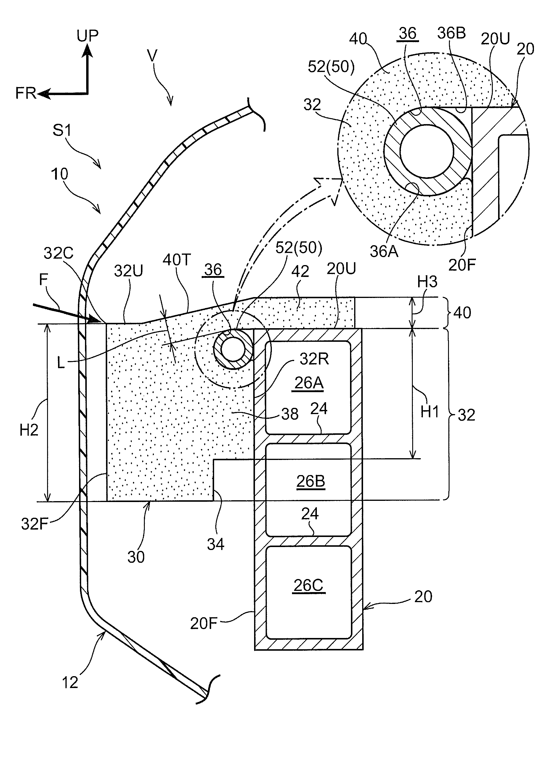
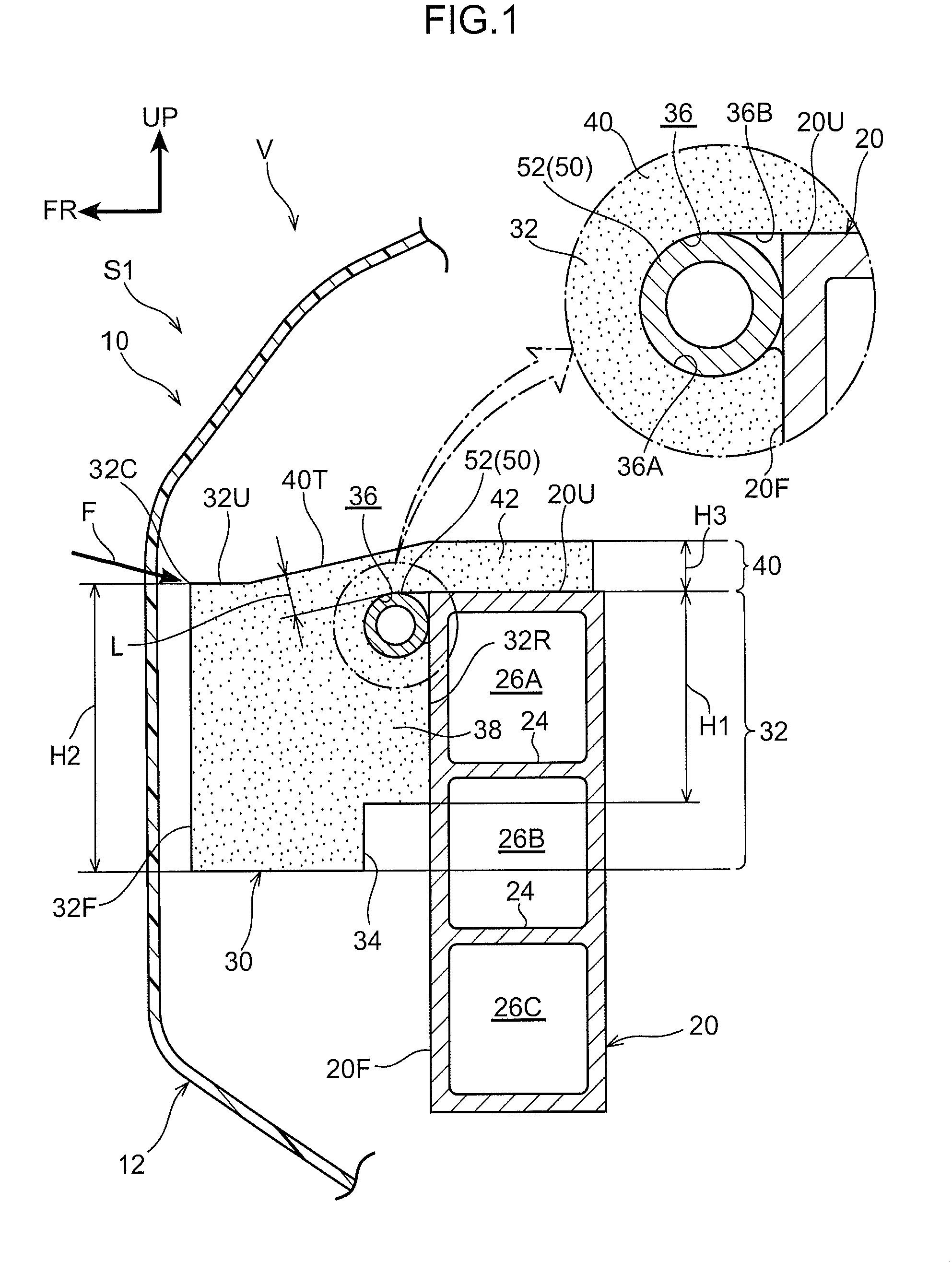
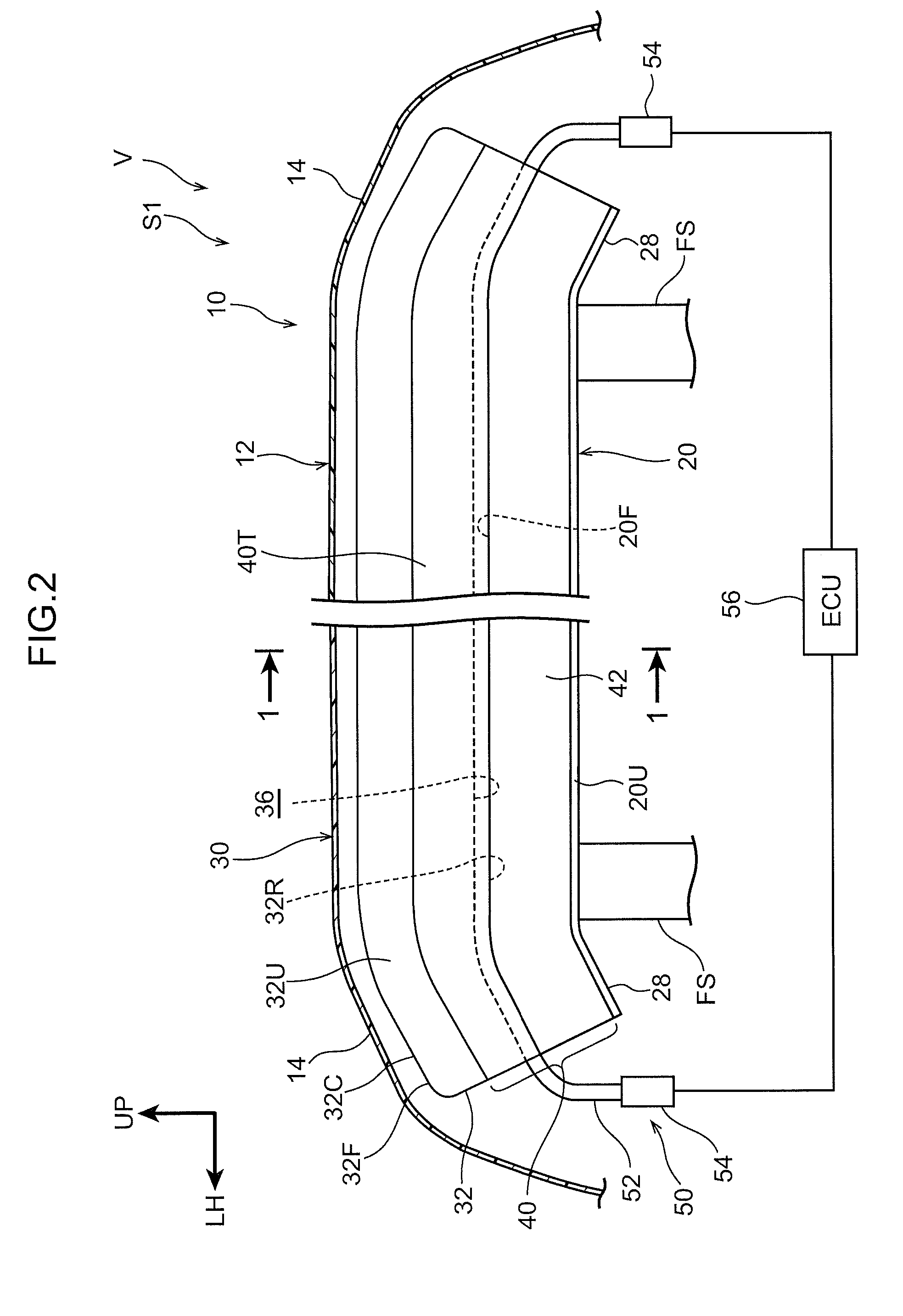
[0048]Explanation follows regarding a front bumper 10 of a vehicle (automobile) V applied with a vehicle bumper structure S1 including a pressure tube-type pedestrian collision detection sensor 50 according to a first exemplary embodiment, with reference to FIG. 1 and FIG. 2. In the drawings, the arrow FR indicates the vehicle front side, the arrow LH indicates the vehicle left side (one vehicle width direction side), and the arrow UP indicates the vehicle upper side as appropriate. Unless otherwise stated, reference below simply to front-rear, up-down, and left-right directions refers to the front-rear of the vehicle front-rear direction, the up-down of the vehicle up-down direction, and the left and right of the vehicle (when facing forward).

[0049]As illustrated in FIG. 1 and FIG. 2, the front bumper 10 is disposed at a front end section of the vehicle V. Thus in the present exemplary embodiment, the “front side” corresponds to the “vehicle front-rear direction outer side” of tech...

second exemplary embodiment

[0085]Explanation follows regarding a vehicle bumper structure S2 including a collision detection sensor 50 according to a second exemplary embodiment, with reference to FIG. 3. The second exemplary embodiment is configured similarly to the first exemplary embodiment, with the exception of the points described below. Note that same reference numerals are appended to components with similar configurations to those in the first exemplary embodiment.

[0086]Namely, in the second exemplary embodiment, a lower absorber 60 is provided at the lower side of the upper absorber 30. The upper absorber 30 and the lower absorber 60 are coupled together as a single unit by a coupling section 62, and an absorber 64 is configured by the upper absorber 30, the lower absorber 60, and the coupling section 62. Specific explanation follows below.

[0087]In the upper absorber 30, the up-down dimension of the absorber main body 32 is set smaller than in the first exemplary embodiment, and the step portion 34 ...

third exemplary embodiment

[0096]Explanation follows regarding a vehicle bumper structure S3 including a collision detection sensor 50 according to a third exemplary embodiment, with reference to FIG. 4. The third exemplary embodiment is similarly configured to the first exemplary embodiment, with the exception of the points described below. Note that same reference numerals are appended to components with similar configurations to those in the first exemplary embodiment.

[0097]Namely, in the third exemplary embodiment, a bracket 80, serving as “another member” is provided between the bumper reinforcement 20 and the upper absorber 30. In other words, the upper absorber 30 is fixed to the front face 20F of the bumper reinforcement 20 through the bracket 80.

[0098]The bracket 80 is formed in an elongated shape with its length direction along the vehicle width direction, and is disposed following the front face 20F of the bumper reinforcement 20. The bracket 80 is formed in a substantially rectangular shape in a c...


PUM


Abstract

In a vehicle bumper structure including a pressure tube-type pedestrian collision detection sensor according to technology disclosed herein, the vehicle bumper structure includes a bumper reinforcement, a pressure tube-type pedestrian collision detection sensor, and an upper absorber. The upper absorber includes an absorber main body, an absorber upper end portion that is integrally provided to the vehicle upper side of the absorber main body, and includes a projecting portion projecting toward the vehicle front-rear direction inner side with respect to the absorber main body at the vehicle upper side of the bumper reinforcement, and a groove portion that is formed at a vehicle front-rear direction inner side portion of the absorber main body, that is disposed adjacent to the vehicle lower side of the absorber upper end portion, that is open toward the vehicle front-rear direction inner side or the vehicle lower side, and that retains a pressure tube.

Description

CROSS-REFERENCE TO RELATED APPLICATION[0001]This application claims priority under 35 USC 119 from Japanese Patent application No. 2014-162445 filed Aug. 8, 2014, the disclosure of which is incorporated by reference herein.BACKGROUND[0002]1. Technical Field[0003]Technology disclosed herein relates to a vehicle bumper structure including a pressure tube-type pedestrian collision detection sensor.[0004]2. Related Art[0005]In a vehicle bumper structure including a pressure tube-type pedestrian collision detection sensor described in International Publication (WO) No. 2012 / 113362, an absorber is disposed adjacent to a vehicle front side of bumper reinforcement. A groove portion open toward the vehicle rear side is formed to the absorber, and a pressure tube is installed (fitted) inside the groove portion. When the pressure tube deforms during a collision between the vehicle and a colliding body, pressure sensors provided at both length direction end portions of the pressure tube output ...

Claims


Application Information

Patent Timeline
Patent Type & Authority Applications(United States)
IPC IPC(8): B60R19/48B60R21/013B60R21/34
CPCB60R19/483B60R21/013B60R21/34B60R19/023B60R19/22B60R19/18B60R21/0136B60R2019/186B60R2019/1873
Inventor NARITA, SOTARO
Owner TOYOTA JIDOSHA KK
Why Eureka
Try Eureka