Vehicle control device

Active Publication Date: 2016-02-11
TOYOTA JIDOSHA KK
View PDF10 Cites 84 Cited by
  • Summary
  • Abstract
  • Description
  • Claims
  • Application Information

AI Technical Summary

Benefits of technology

[0015]According to the present invention, it is possible to provide a vehicle control device that can appropriatel

Problems solved by technology

In the device described above, there is a problem in that it is not possible to appropriately urge the driver to switch the travel mode from the autonomous travel to the manual travel by the driver.
In both of these cases, it is not always appropriate that notification timings to urge the driver to switch the tr

Method used


Image

  • Vehicle control device
  • Vehicle control device
  • Vehicle control device

Examples


Example

[0020]Hereinafter, an embodiment of the present invention will be described with reference to the drawings. In the description below, the same reference signs will be given to the same or corresponding elements and the description thereof will not be repeated.

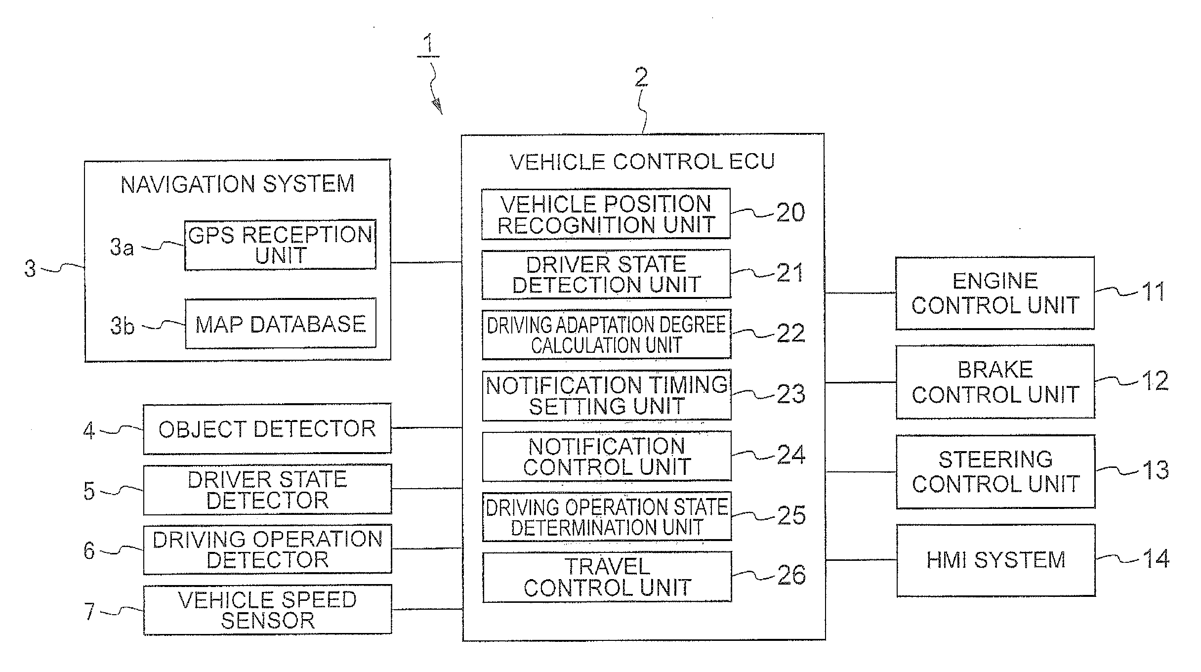
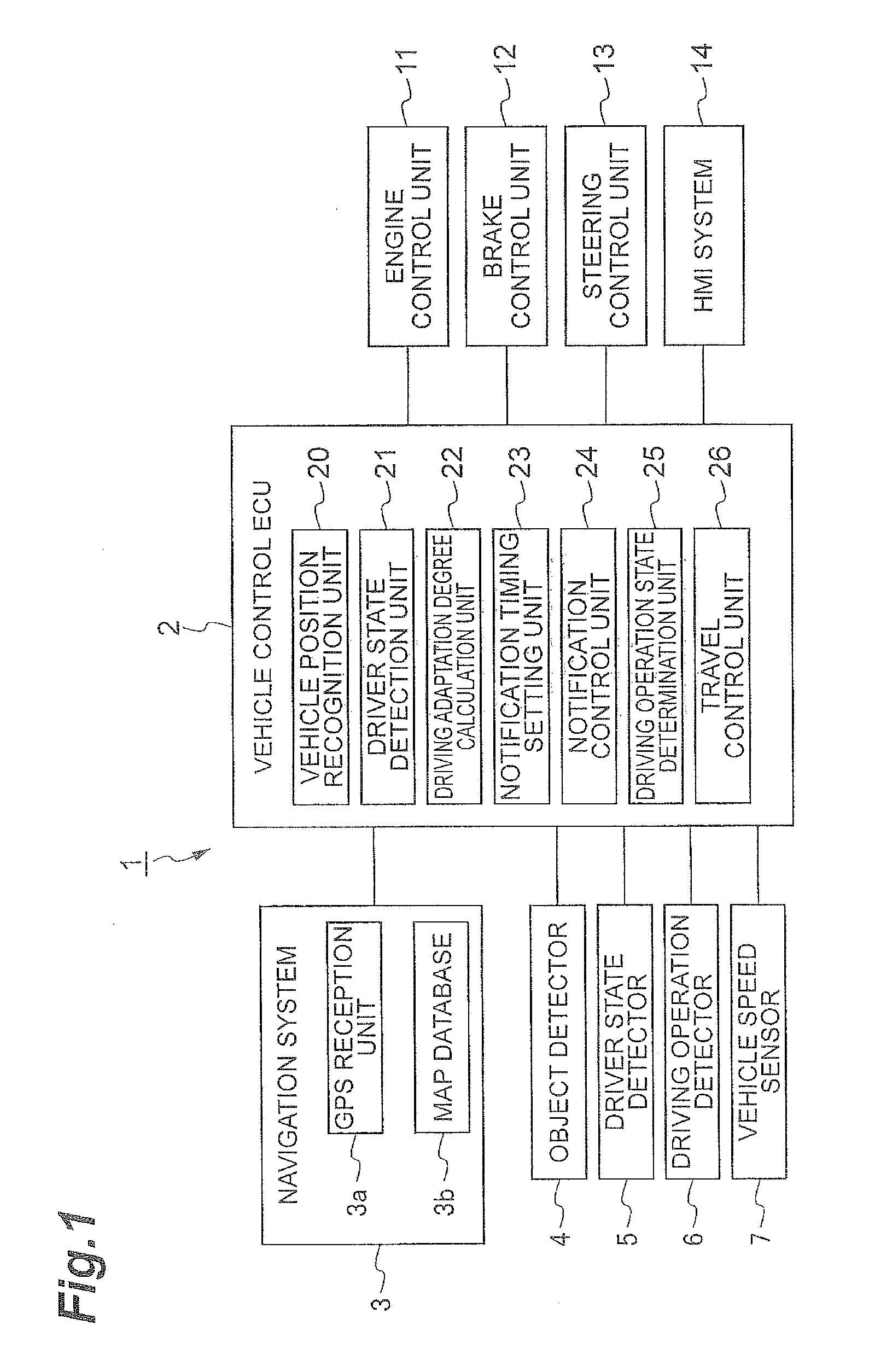
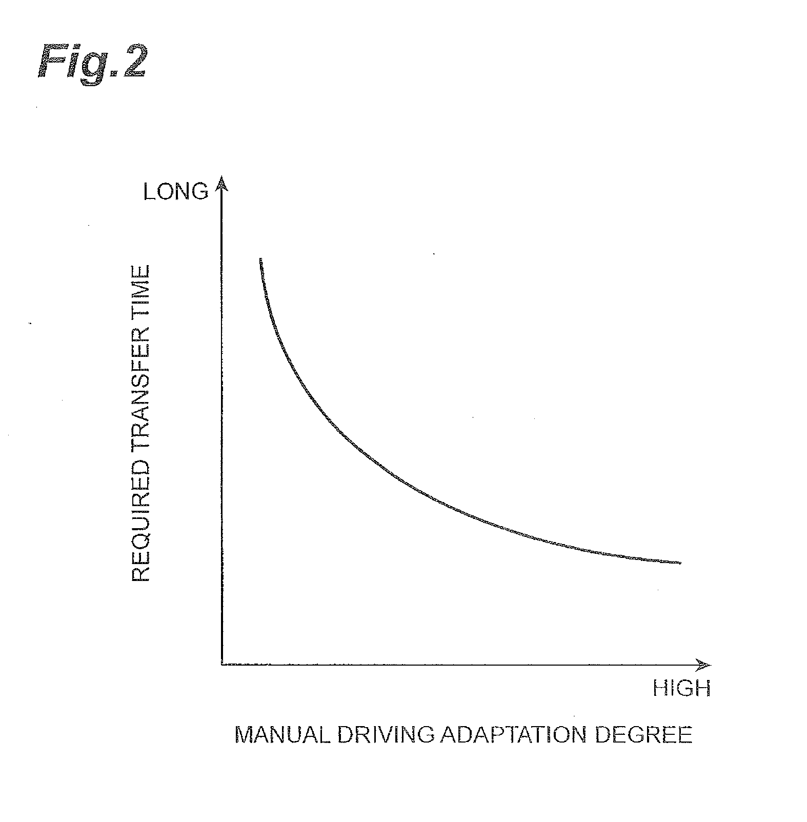
[0021]FIG. 1 is a diagram illustrating an overall configuration of a vehicle control device 1 in an embodiment of the present invention. FIG. 2 is an explanatory diagram of an object detection operation in the vehicle control device 1.

[0022]As illustrated in FIG. 1, the vehicle control device 1 in the embodiment of the present invention is a device mounted on a vehicle, causes the vehicle to automatically travel, and enables an automatic travel of the vehicle by the automatic driving to be switched to the manual travel by the driver. For example, the vehicle control device 1 can cause the vehicle to automatically travel by an automatic driving of the vehicle by performing an automatic travel control. In addition, the vehicle co...


PUM


Abstract

In a vehicle control device that is configured to be capable of switching from an automatic travel of the vehicle to manual travel by a driver, a manual driving adaptation degree of a driver during an automatic travel is calculated based on a driver state (S16), a notification timing is set such that the notification timing is earlier as the manual driving adaptation degree becomes lower (S18), and the automatic travel end notification is given to the driver at the set notification timing (S20).

Description

BACKGROUND OF THE INVENTION[0001]1. Field of the Invention[0002]The present invention relates to a vehicle control device.[0003]2. Related Background Art[0004]As a device relating to a vehicle control, for example, as disclosed in Japanese Unexamined Patent Application Publication No. 9-161196, a device that enables the vehicle to autonomously travel and performs control processing in which the autonomous travel of the vehicle is switched to manual travel by a driver is known.[0005]The device performs an operation of urging the driver to switch the travel mode to the manual travel when the vehicle approaches a point where the travel mode is scheduled to be switched to the manual travel.SUMMARY[0006]In the device described above, there is a problem in that it is not possible to appropriately urge the driver to switch the travel mode from the autonomous travel to the manual travel by the driver. For example, in the autonomous travel, there are two cases according to a wakefulness stat...

Claims


Application Information

Patent Timeline
IPC IPC(8): B60W50/00G05D1/00B60W50/08B60W50/14
CPCG05D1/0061G05D1/0088B60W2600/00B60W50/0098B60W50/14B60W50/082B60W10/06B60W10/18B60W10/20B60W30/14B60W30/182B60W40/02B60W40/08B60W40/09B60W40/105G05D1/02B60W2710/30B60W2710/20B60W2710/18B60W2710/06B60W2540/00B60W2540/26B60W2520/10B60W2040/0818B60W2050/146B60W2050/143B60W2556/50B60W2554/00B60K28/066B60W2556/00B60W2540/229B60W2540/223B60W2540/221B60W60/0053B60W60/0059B60W2540/225B60W2420/403B60W30/143
Inventor SATO, JUNIWASAKI, MASAHIRO
Owner TOYOTA JIDOSHA KK
Why Eureka
Try Eureka