Organic el display device

a display device and organic technology, applied in the direction of thermoelectric device junction materials, semiconductor devices, electrical apparatus, etc., can solve the problems of insufficient adhesive properties between organic materials and inorganic materials, infiltration into pin holes, deterioration of organic layers, etc., to achieve the effect of efficiently preventing moisture from infiltrating into organic layers and organic layers

Active Publication Date: 2016-02-11
JAPAN DISPLAY INC
View PDF1 Cites 64 Cited by
  • Summary
  • Abstract
  • Description
  • Claims
  • Application Information

AI Technical Summary

Benefits of technology

[0006]In a process of forming the first substrate, a pin hole may be caused in a barrier due to a foreign particle such as dust in some cases. When the pin hole is caused, moisture infiltrates into the pin hole and thereby an organic layer is deteriorated. The inventors of the present application have examined a multi-barrier structure formed of a plurality of barrier layers which are formed of inorganic materials, and an organic barrier which is formed of organic materials. The first barrier layer covers the organic layer. The organic barrier is disposed on a first inorganic barrier layer. When foreign particle exists on the first inorganic barrier layer, the organic barrier is formed so as to surround the foreign particle. A second inorganic barrier layer covers the first inorganic barrier layer and the organic barrier. According to the multi-barrier, the organic barrier is formed around the foreign particle, and an uneven surface (that is, a difference in level) around the foreign particle is decreased by the organic barrier. Therefore, even when the thickness of the second inorganic barrier layer is made small, the second inorganic barrier layer can completely cover the foreign particle. As a result, it is possible to efficiently prevent moisture from infiltrating into the organic layer. The organic barrier is, for example, formed as follows. A solvent including the organic material is made into a sprayed state and then sprayed onto the first inorganic barrier layer. The organic material on the first inorganic barrier layer is moved on the first inorganic barrier layer due to surface tension thereof, thereby forming a liquid droplet. When the foreign particle exists, the organic material coheres around the foreign particle due to the surface tension.

Problems solved by technology

When the pin hole is caused, moisture infiltrates into the pin hole and thereby an organic layer is deteriorated.
Incidentally, adhesive properties between the organic material and the inorganic material are not satisfactory, and thus the organic barrier and the inorganic barrier layer are likely to be separated.

Method used


Image

  • Organic el display device
  • Organic el display device
  • Organic el display device

Examples


Embodiment Construction

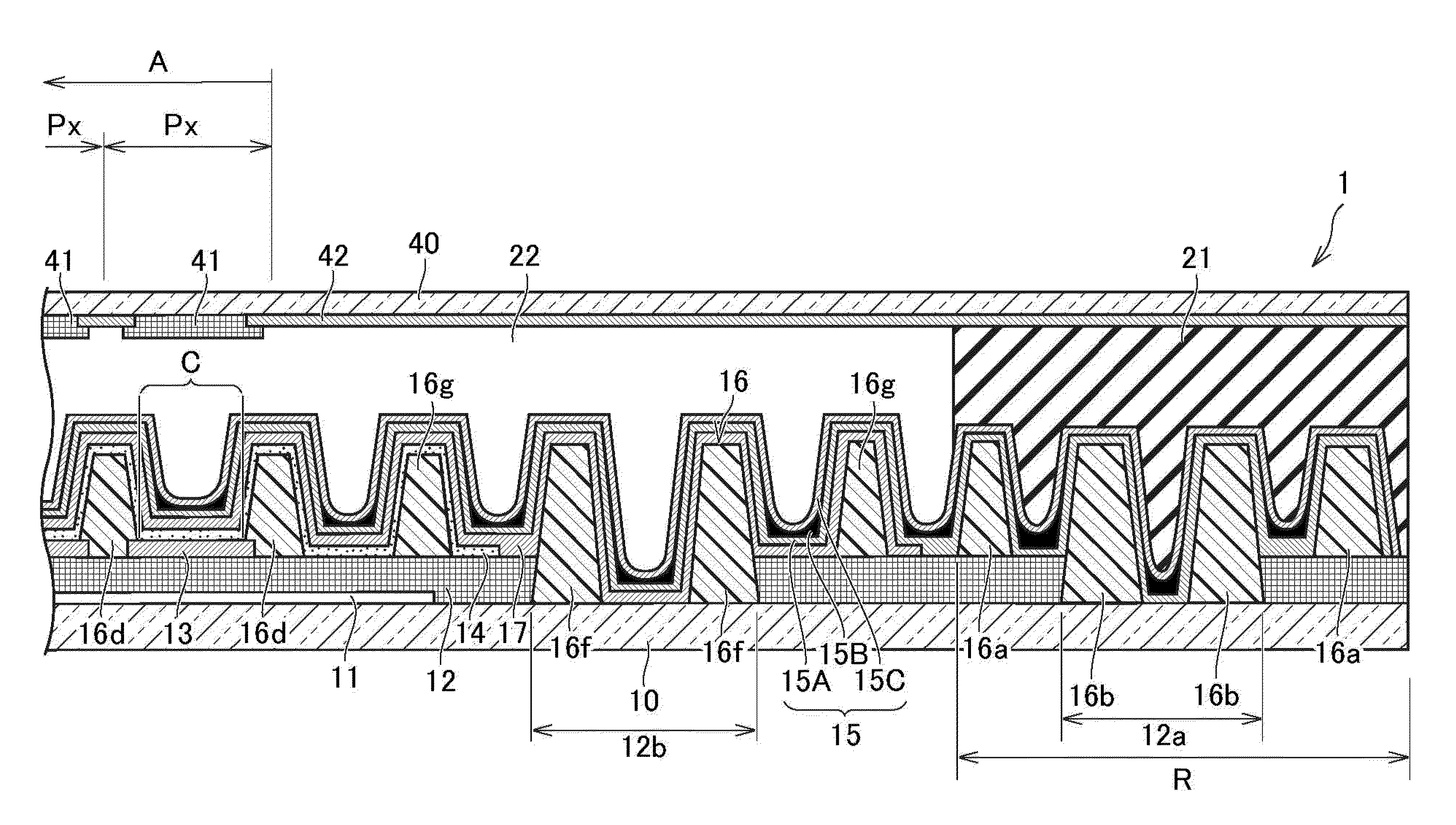
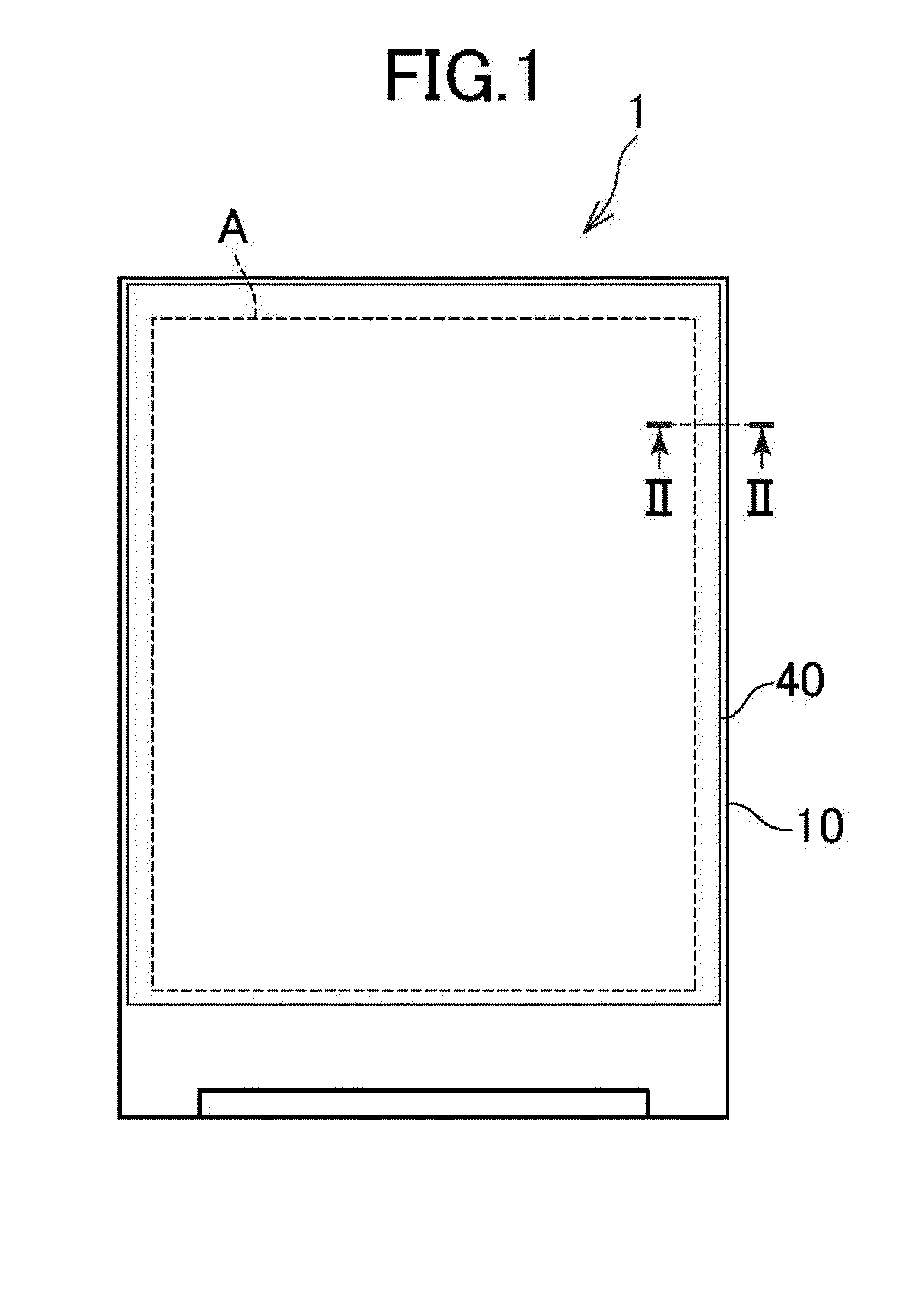
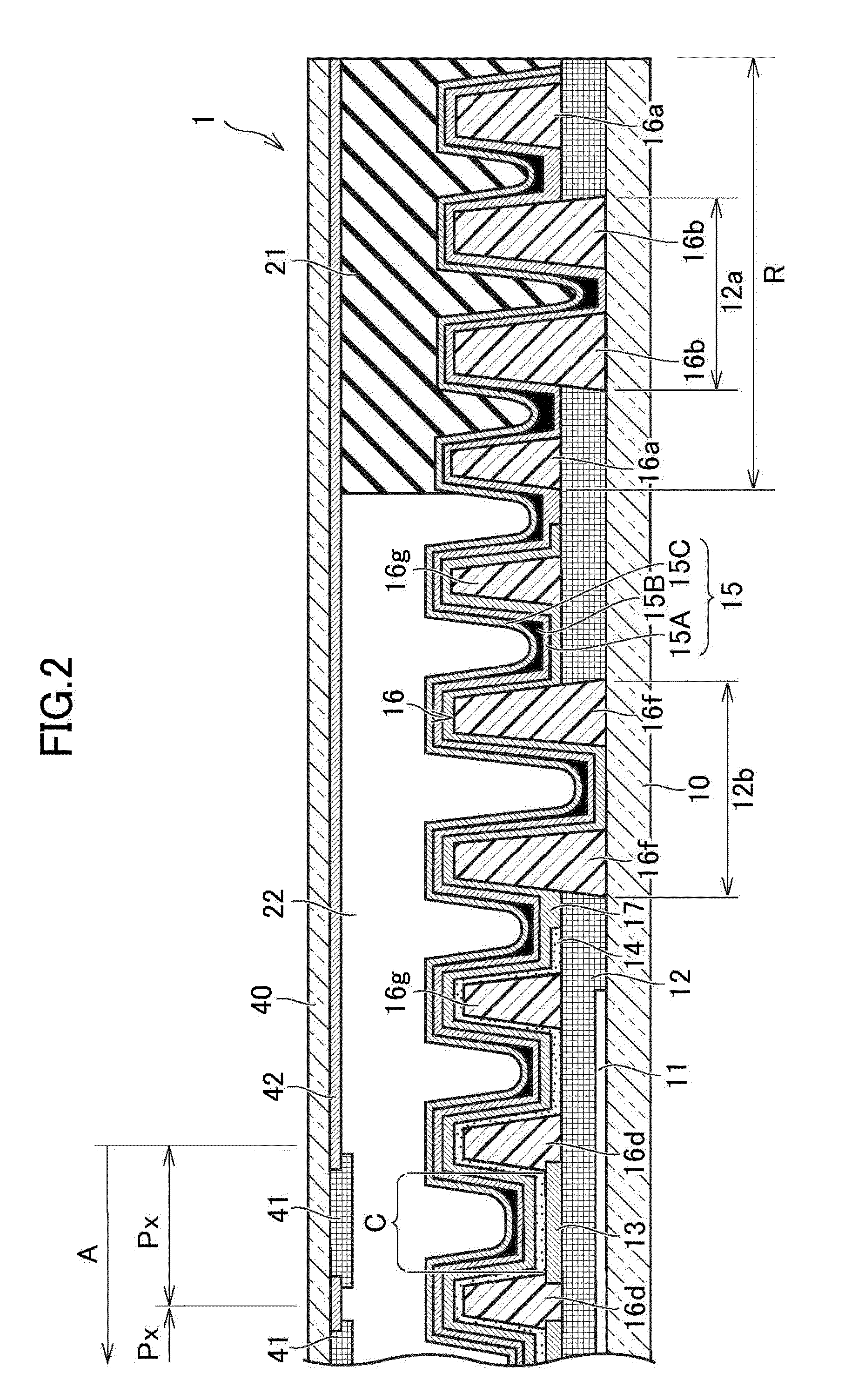
[0024]Hereinafter, an embodiment of the invention will be described. FIG. 1 is a plan view of an organic EL display 1 according to the invention. FIG. 2 is a sectional view taken along line II-II shown in FIG. 1. In the present specification, an “upper direction” indicates a direction toward a second substrate 40 from a first substrate 10, a “lower direction” indicates a direction toward the first substrate 10 from the second substrate 40.

[0025]Disclosure of the present specification is merely only an example. Thus, embodiments which maintain the spirit of the invention and are easily modified by those skilled in the art is surely contained in the scope of the invention. In addition, a width, a thickness, and a shape of each portion shown in the drawings may be schematically represented. Therefore, the description of the width, and the thickness of each portion in the drawings is merely an example, and does not limit the interpretation of the invention.

[0026]As illustrated in FIG. 2...


PUM


Abstract

A bank layer includes projecting portions swollen toward in a thickness direction of a first substrate in an adhesion area. A multi-barrier includes a portion, in which a organic barrier is not disposed, on an upper side of the projecting portions. Therefore, it is possible to obtain, in the adhesion area, a portion in which a first inorganic barrier layer and a second inorganic barrier layer directly come in contact with each other. In an organic EL display device including the multi-barrier formed of an organic material and an inorganic material, it is possible to prevent two facing substrates from being separated from each other.

Description

CROSS-REFERENCE TO RELATED APPLICATION[0001]The present application claims priority from Japanese application JP2014-163679 filed on Aug. 11, 2014, the content of which is hereby incorporated by reference into this application.BACKGROUND OF THE INVENTION[0002]1. Field of the Invention[0003]The present invention relates to an organic EL display device.[0004]2. Description of the Related Art[0005]Organic EL display devices include a first substrate on which an organic layer including a light emitting layer is formed, and a second substrate facing the first substrate. A sealing material is disposed along an outer periphery of the second substrate. The outer periphery of the second substrate is bonded to the first substrate by using the sealing material. For example, JP2006-004909A, JP2002-311853A, and JP2007-200838A disclose the sealing material. When moisture infiltrates into the organic layer, the organic layer is deteriorated, and thereby the quality of an image is deteriorated. The...

Claims


Application Information

Patent Timeline
Patent Type & Authority Applications(United States)
IPC IPC(8): H01L51/52H01L27/32
CPCH01L27/32H01L51/5253H10K59/122H10K59/124H10K50/8426H10K50/844
Inventor KAMIYA, AKINORIFUKUDA, KAICHIKATO, DAISUKE
Owner JAPAN DISPLAY INC
Why Eureka
Try Eureka