Image forming apparatus, image forming method, and non-transitory recording medium

Inactive Publication Date: 2016-02-11
RICOH KK
View PDF4 Cites 4 Cited by
  • Summary
  • Abstract
  • Description
  • Claims
  • Application Information

AI Technical Summary

Benefits of technology

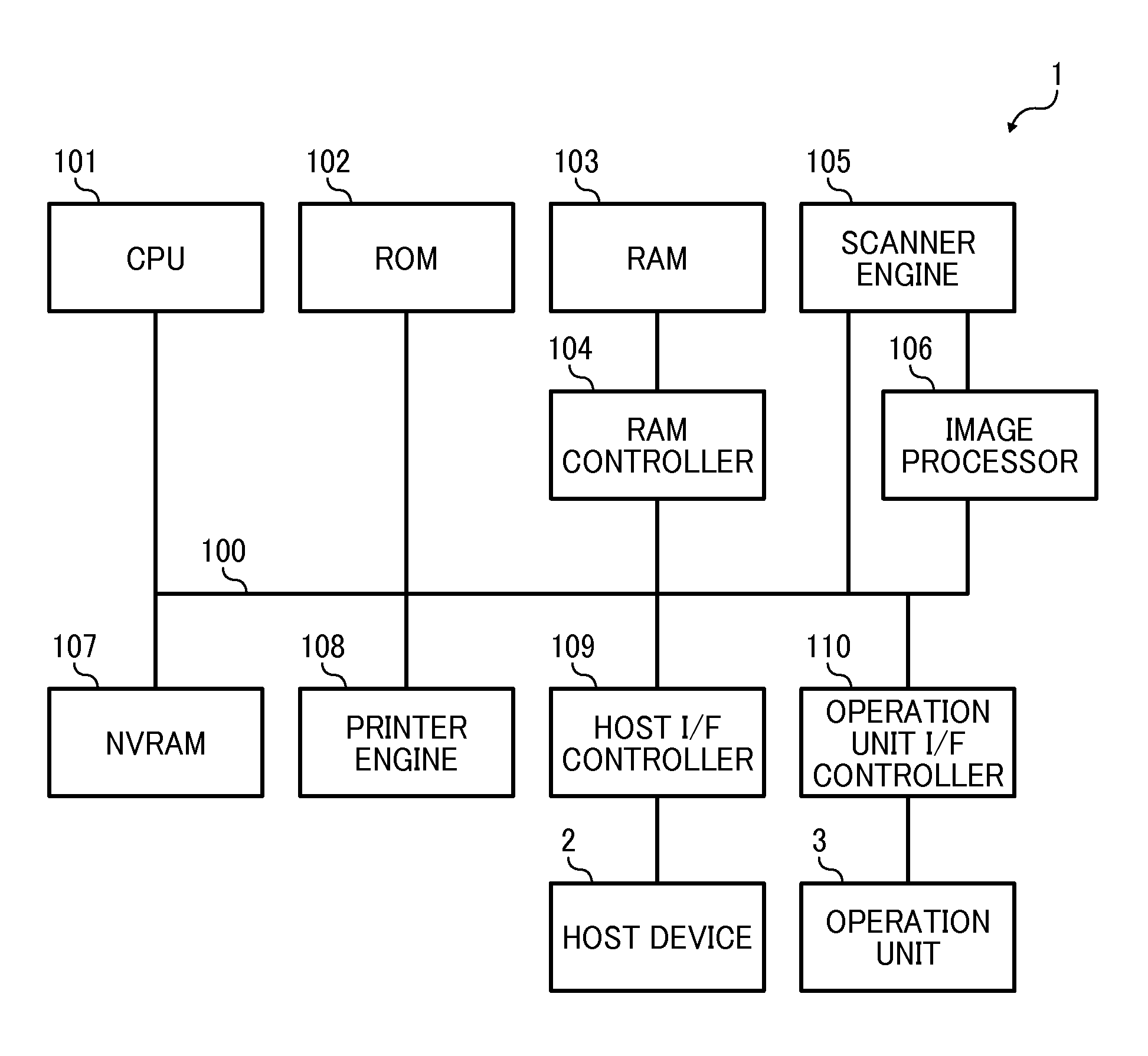
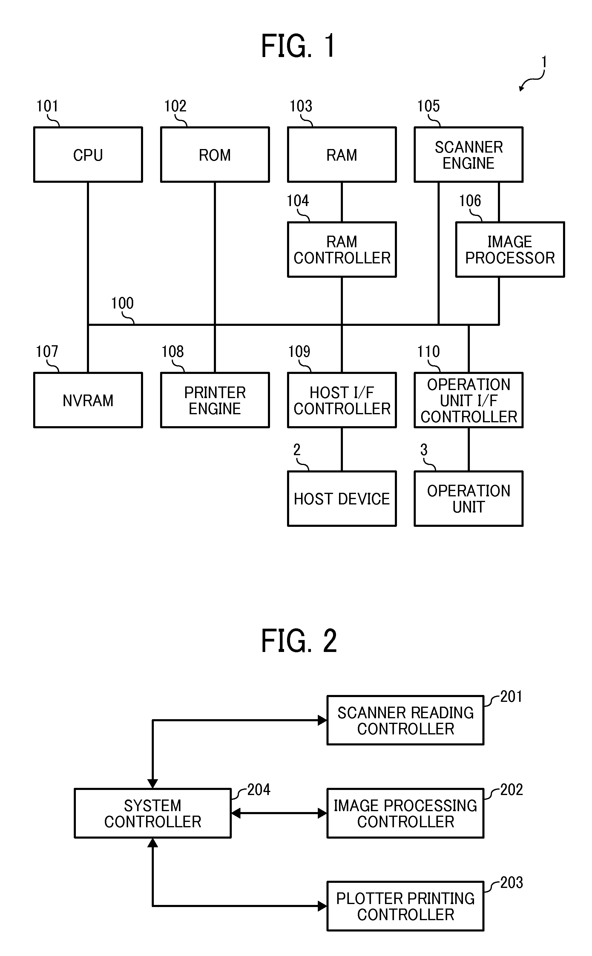
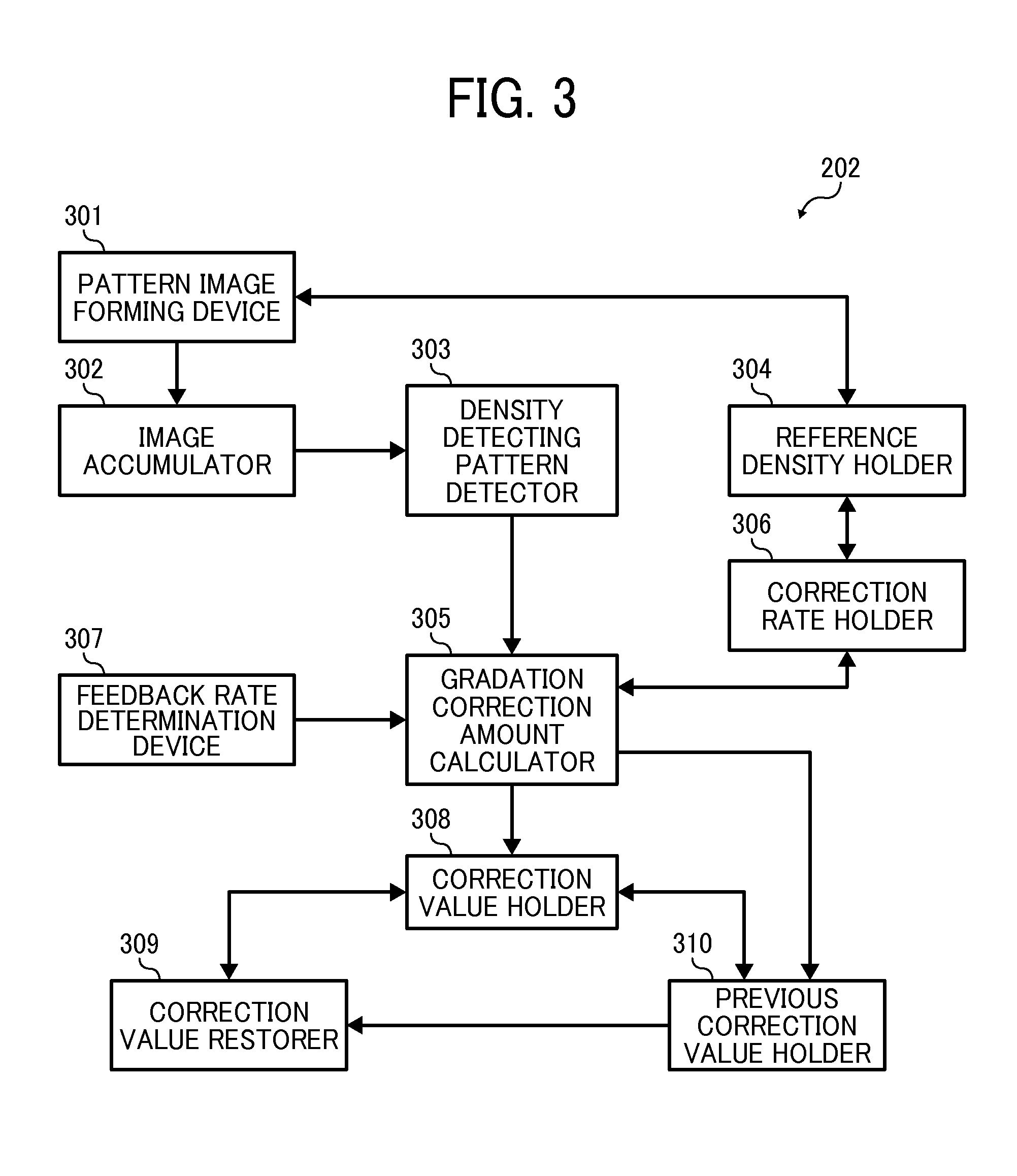
The present invention provides an image forming apparatus that can accurately adjust the density of an image for better quality control. It includes a pattern image forming device, a density information detector, and a gradation correction amount calculator. The pattern image forming device creates a pattern image for gradation correction, the density information detector detects density information from the recording medium where the pattern image is formed, and the gradation correction amount calculator uses this information and a feedback rate to determine the appropriate gradation correction amount. This invention allows for faster and more accurate adjustment of the image density, resulting in better quality printed materials.

Problems solved by technology

Therefore, an apparatus having multiple dither patterns should be subjected to calibration multiple times. The multiple times of calibration disadvantageously requires a large amount of time.

Method used


Image

  • Image forming apparatus, image forming method, and non-transitory recording medium
  • Image forming apparatus, image forming method, and non-transitory recording medium
  • Image forming apparatus, image forming method, and non-transitory recording medium

Examples


Embodiment Construction

[0022]The terminology used herein is for the purpose of describing particular embodiments only and is not intended to be limiting of the present invention. As used herein, the singular forms “a”, “an” and “the” are intended to include the plural forms as well, unless the context clearly indicates otherwise. It will be further understood that the terms “includes” and / or “including”, when used in this specification, specify the presence of stated features, integers, steps, operations, elements, and / or components, but do not preclude the presence or addition of one or more other features, integers, steps, operations, elements, components, and / or groups thereof.

[0023]In describing example embodiments shown in the drawings, specific terminology is employed for the sake of clarity. However, the present disclosure is not intended to be limited to the specific terminology so selected and it is to be understood that each specific element includes all technical equivalents that operate in a s...


PUM


Abstract

An image forming apparatus is provided. The image forming apparatus includes a pattern image forming device, a density information detector, and a gradation correction amount calculator. The pattern image forming device forms a pattern image for use in gradation correction on a recording medium. The density information detector detects density information from the recording medium on which the pattern image is formed by the pattern image forming device. The gradation correction amount calculator calculates a gradation correction amount using the density information detected by the density information detector and a feedback rate in accordance with differences among two or more density adjustment modes.

Description

CROSS-REFERENCE TO RELATED APPLICATIONS[0001]This patent application is based on and claims priority pursuant to 35 U.S.C. §119(a) to Japanese Patent Application Nos. 2014-159821 and 2015-126441, filed on Aug. 5, 2014 and Jun. 24, 2015, respectively, in the Japan Patent Office, the entire disclosure of each of which is hereby incorporated by reference herein.BACKGROUND[0002]1. Technical Field[0003]The present disclosure relates to an image forming apparatus, an image forming method, and a non-transitory recording medium.[0004]2. Description of the Related Art[0005]It is known that image forming apparatuses, such as laser printer and MFP (Multi Function Printer), output images with variation due to their temporal change or individual difference. One reason for the variation in output images is fluctuations in dot gain that is caused by temporal change of the apparatus.[0006]The degree of density change caused by the fluctuations in dot gain depends on the number and shape of dither. ...

Claims


Application Information

Patent Timeline
IPC IPC(8): G06K15/02H04N1/407H04N1/00
CPCH04N1/4078G06K15/027H04N2201/0094H04N1/00068H04N1/00087G06K15/1822H04N1/6041
Inventor KOBAYASHI, RYO
Owner RICOH KK
Why Eureka
Try Eureka