Method of filling liquid crystal display panel with liquid crystal and liquid crystal filling system performing the same
Inactive Publication Date: 2005-09-22
SAMSUNG DISPLAY CO LTD
View PDF4 Cites 7 Cited by
Summary
Abstract
Description
Claims
Application Information
AI Technical Summary
This helps you quickly interpret patents by identifying the three key elements:
Problems solved by technology
Method used
Benefits of technology
Benefits of technology
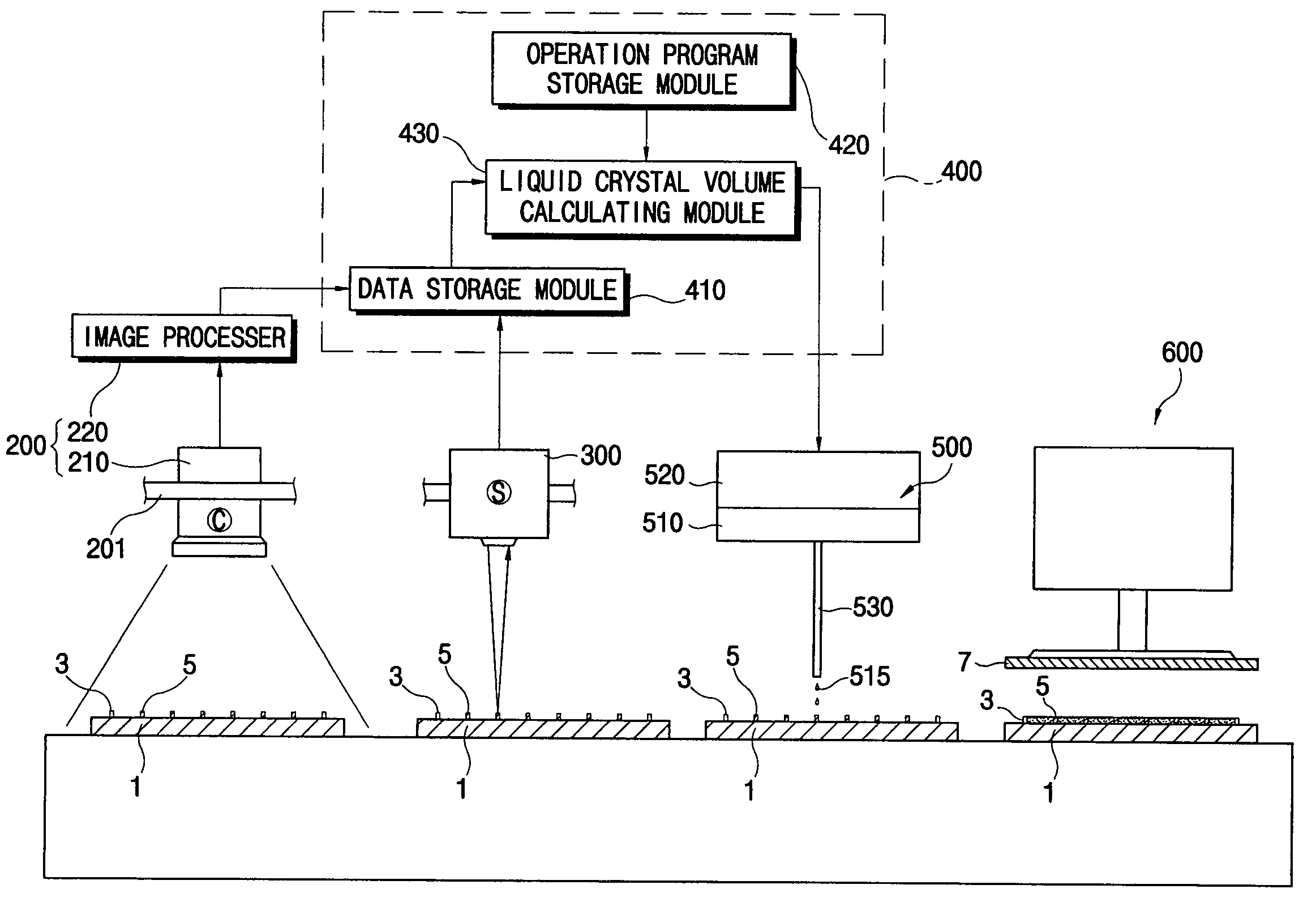
[0024] The present invention has been made to solve the above problems of the prior arts, therefore, it is a one feature of the present invention to provide a method of filling liquid crystal into a liquid crystal display panel, which reduces process failures such as shortage of the liquid crystal supplied into the liquid crystal display panel and overflow of the liquid crystal. In the method of filling the liquid crystal, process parameters influencing an amount of the liquid crystal to be supplied into the liquid crystal display panel may be precisely measured, the amount of the liquid crystal to be supplied is calculated based on the measured process parameters, and the calculated amount of the liquid crystal is supplied into the liquid crystal display panel.
[0025] In addition, it is a another feature of the present invention to provide a liquid crystal filling system that reduces process failures such as shortage of the liquid crystal supplied into the liquid crystal display panel and overflow of the liquid crystal. In the liquid crystal filling system, process parameters influencing an amount of the liquid crystal to be supplied may be precisely measured, the amount of the liquid crystal to be supplied is calculated based on the measured process parameters, and the calculated amount of the liquid crystal is supplied into the liquid crystal display panel.
[0029] As described above, according to the present invention, liquid crystal is filled between two substrates so that the number of the steps for sealing the liquid crystal can be reduced, and the processing time required for sealing the liquid crystal can be minimized. In addition, bubbles generated while the liquid crystal is insufficiently filled between two substrates can be reduced, and overflowing of liquid crystal due to excessive amount of liquid crystal can be prevented.
Problems solved by technology
However, an excessive amount of liquid crystal may be supplied into the cell gap.
However, according to the second liquid crystal filling method, bubbles are generated inside the liquid crystal display panel or the liquid crystal overflows the liquid crystal display panel.
For example, when an excessive amount of liquid crystal is supplied into the color filter substrate, the excessive amount of liquid crystal overflows outside of the liquid crystal display panel.
On the contrary, when the liquid crystal is insufficiently supplied into the color filter substrate, a bubble area is formed inside the liquid crystal display panel.
Since a random number of spacers are attached to the region enclosed by the seal line, measuring the total volume of the spacers is difficult.
For this reason, it is difficult to precisely calculate the total volume of the spacers.
Therefore, the amount of liquid crystal to be supplied may not be precisely calculated.
Therefore, it is difficult to precisely calculate the total volume of the spacers and the amount of liquid crystal to be supplied.
Method used
Image
Click on the blue label to locate the original text in one second.
Reading with bidirectional positioning of images and text.
Examples
embodiment 1
[0063]FIG. 4 is a flow chart showing a method of obtaining a second volume according to a first exemplary embodiment of the present invention.
[0064] Referring to FIG. 4, the second volume is obtained through two steps 22 and 24.
[0065] The number of the spacers disposed in the region enclosed by the seal line is obtained in step 22. The spacers may have a spherical shape and may be randomly scattered in the region disposed on the first substrate.
[0066]FIG. 5 is a flow chart showing a method of obtaining a number of spherical spacers according to a first exemplary embodiment of the present invention.
[0067] Referring to FIG. 5, the number of spacers can be obtained through steps 22A, 22B, 22C and 22D.
[0068] A second image of the spacers is obtained in step 22A. The spacers may have a spherical shape. The second image is temporarily stored in the storage unit.
[0069] In addition, in step 22B, the second image is transformed into image data by an image processing technique and are t...
embodiment 2
[0074]FIG. 6 is a flow chart showing the method of obtaining a second volume according to a second exemplary embodiment of the present invention.
[0075] Referring to FIG. 6, the second volume is obtained through three steps 25, 27 and 29.
[0076] A second area of the spacers in the region enclosed by the seal line is obtained in step 25.
[0077] A predetermined number of spacers having a column shape are disposed at predetermined positions in the region enclosed by the seal line. The column-shape spacer may be formed through a process of patterning photosensitive material.
[0078] According to the preferred exemplary embodiment of the present invention, the spacer may have a cylindrical shape.
[0079]FIG. 7 is a flow chart showing a method of obtaining a second area of column-shape spacers according to a second exemplary embodiment of the present invention.
[0080] Referring to FIG. 7, the second area of the column-shape spacers is obtained through three steps 25A, 25B, and 25C.
[0081] A...
PUM
Abstract
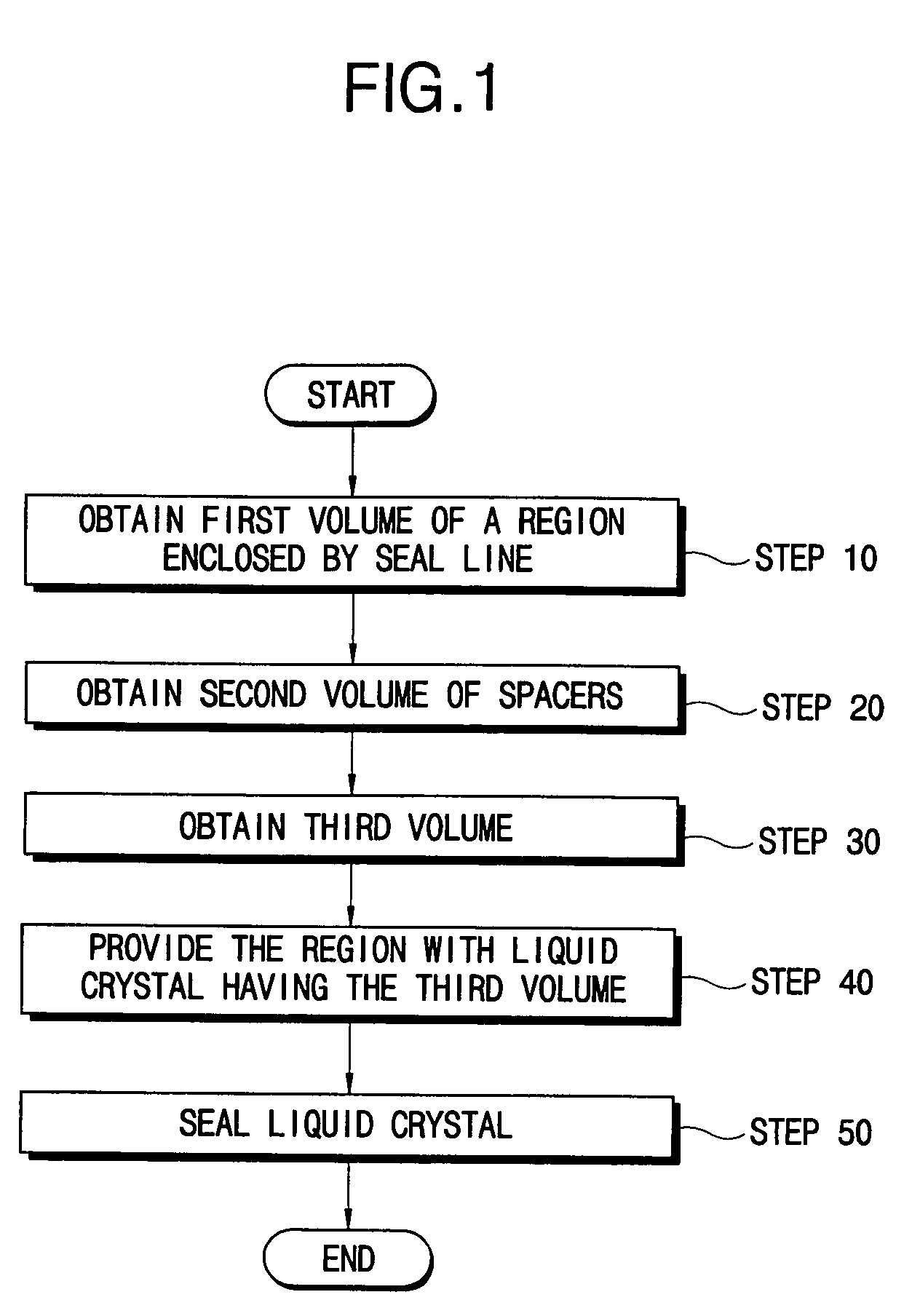
In a method of filling a liquid crystal display panel with liquid crystal and a liquid crystal filling system using the method, a seal line and spacers are formed on a color filter substrate. A first volume defined by the seal line and a second volumes defined by the spacers are obtained. An amount of liquid crystal to be supplied into a region enclosed by the seal line is precisely calculated based on the first and second volumes. Shortage of the liquid crystal supplied into the LCD panel and overflow of the liquid crystal can be avoided. Accordingly, the steps for supplying the liquid crystal into the LCD panel may be reduced, and simultaneously peripheral regions of the LCD panel be prevented from being contaminated by the liquid crystal while the liquid crystal is filled into the LCD panel.
Description
CROSS-REFERENCE TO RELATED APPLICATIONS [0001] This application relies for priority upon Korean Patent Application No. 2002-33324 filed on Jun. 14, 2002, the contents of which are herein incorporated by reference in its entirety. BACKGROUND OF THE INVENTION [0002] 1. Field of the Invention [0003] The present invention relates to a method of filling a liquid crystal display panel with liquid crystal and a liquid crystal filling system for performing the same. [0004] 2. Description of the Related Art [0005] Generally, liquid crystal is interposed between a TFT substrate and a color filter substrate of a liquid crystal display panel. [0006] The liquid crystal is affected by an electric field formed between the TFT substrate and the color filter substrate. In detail, the liquid crystal varies the transmissivity of the light supplied from an external light source depending on the electric field applied thereto, so that full-color images required by users can be displayed. [0007] The TFT ...
Claims
Application Information
Patent Timeline
Application Date:The date an application was filed.
Publication Date:The date a patent or application was officially published.
First Publication Date:The earliest publication date of a patent with the same application number.
Issue Date:Publication date of the patent grant document.
PCT Entry Date:The Entry date of PCT National Phase.
Estimated Expiry Date:The statutory expiry date of a patent right according to the Patent Law, and it is the longest term of protection that the patent right can achieve without the termination of the patent right due to other reasons(Term extension factor has been taken into account ).
Invalid Date:Actual expiry date is based on effective date or publication date of legal transaction data of invalid patent.

