Collapsible two-piece olif implant

Active Publication Date: 2016-02-18
SPINESMITH PARTNERS
View PDF3 Cites 5 Cited by
  • Summary
  • Abstract
  • Description
  • Claims
  • Application Information

AI Technical Summary

Benefits of technology

[0008]An embodiment of the invention provides a fusion bearing device that is configured to fit between two adjacent vertebrae, the fusion bearing device having one or more openings to allow access to the end plates of the two

Problems solved by technology

A disadvantage to the patient being flat on their back is that all the abdominal o

Method used


Image

  • Collapsible two-piece olif implant
  • Collapsible two-piece olif implant

Examples


Example

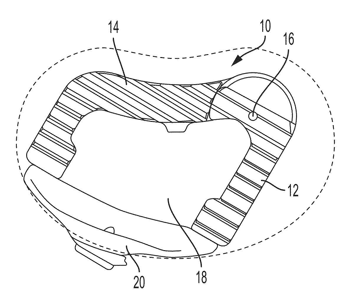
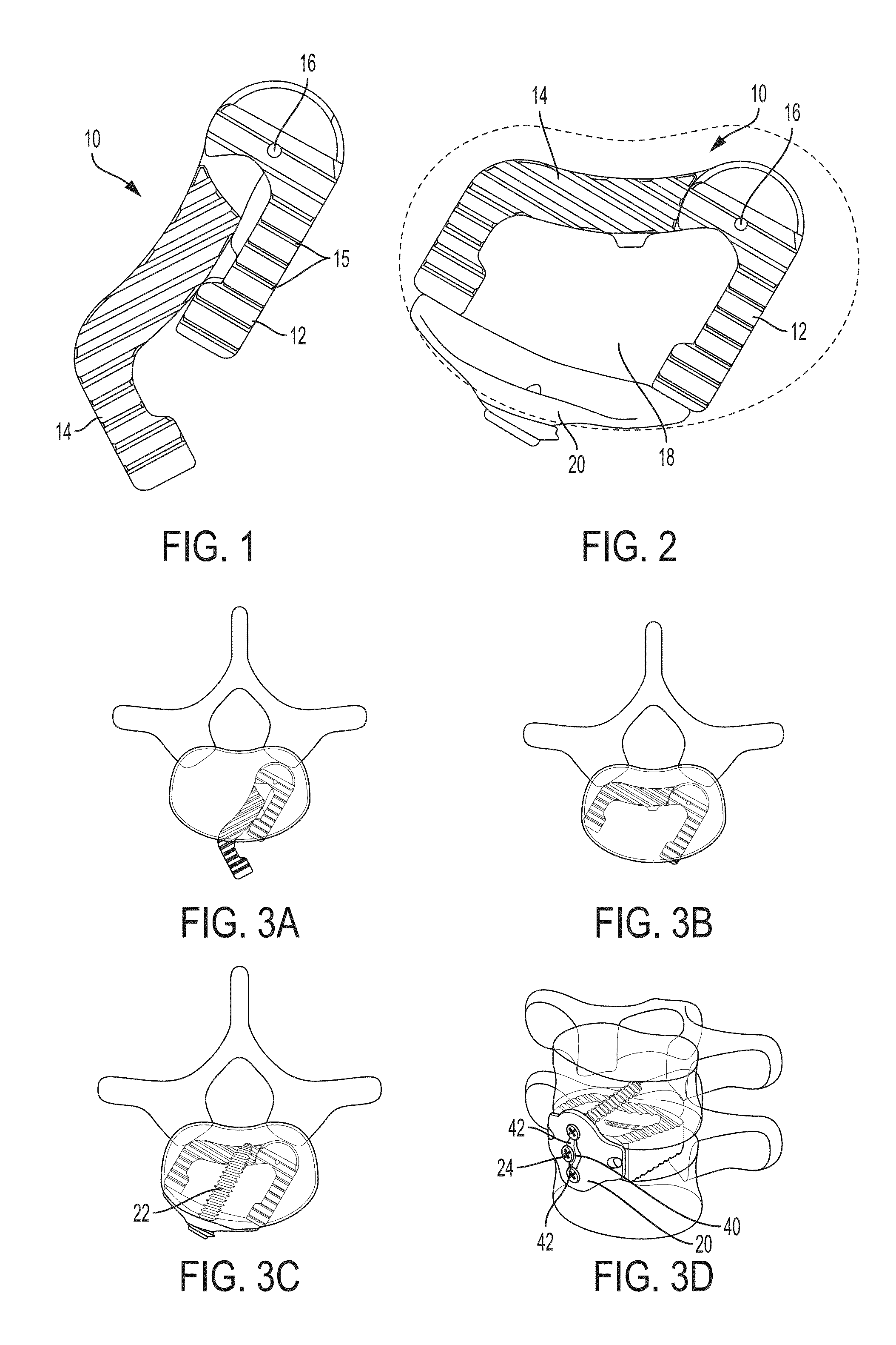
[0016]In an embodiment of the invention, the interbody fusion device comprises a fusion bearing device and a retention device and further comprises two bone screws that pass through the retention device and into the vertebral bodies. When implanted, the construct is flush with the anterior face of the vertebras and provides support and temporary fixation for the ultimate fusion of the vertebral bodies.

[0017]The present invention relates to spinal fusion implants and related spinal fusion procedures for use in cervical and lumbar applications. One type of spinal fusion is interbody fusion. Typically, an interbody fusion procedure places a bone graft between the vertebrae in the area normally occupied by an intervertebral disc. In preparation for a spinal fusion procedure, the intervertebral disc is removed. A device, typically containing a bone promoting matrix, such as allograph bone, may be placed between the vertebra to maintain spine alignment and disc height. Fusion then occurs ...


PUM


Abstract

The invention is directed to an interbody fusion device comprises a load bearing component and a retention component and further comprises two bone screws that pass through the retention device and into the vertebral bodies. When implanted, the construct is flush with the anterior face of the vertebras and provides support and temporary fixation for the ultimate fusion of the vertebral bodies.

Description

CROSS-REFERENCES TO RELATED APPLICATIONS[0001]This Application claims the benefit under 35 U.S.C. §119(e) of U.S. Provisional Patent Application No. 61 / 951,351 filed Mar. 11, 2014 which is incorporated herein by reference in its entirety as if fully set forth herein.BACKGROUND OF THE INVENTION[0002]There is a desire among surgeons to approach the lower lumbar region from an oblique approach, and secondly, a desire to have a more minimally invasive surgical (MIS) procedure.[0003]This approach would locate the patient on their side, vs. flat on their back, as with a typical anterior approach for surgery. A disadvantage to the patient being flat on their back is that all the abdominal organs and vessels must be retracted away to expose the anterior face of the spine. When approaching the spine with the patient on their side, gravity aids in this retraction, naturally pulling the intestines and other vessels out and away from the spine, virtually creating an open space for the surgeon t...

Claims


Application Information

Patent Timeline
IPC IPC(8): A61F2/44
CPCA61F2/442A61F2/4455A61F2002/30471A61F2002/30578A61F2002/30579
Inventor KANA, RICHARD J.DUNWORTH, KEVINROSSMAN, JOHN B.DUARTE, LUIS
Owner SPINESMITH PARTNERS
Why Eureka
Try Eureka