Morphing trailing edge device for an airfoil

a technology of trailing edge device and airfoil, which is applied in the direction of blade accessories, wing adjustment, machine/engine, etc., to achieve the effect of reducing the fuel consumption of the aircra

Active Publication Date: 2016-02-18
AIRBUS OPERATIONS GMBH
View PDF11 Cites 9 Cited by
  • Summary
  • Abstract
  • Description
  • Claims
  • Application Information

AI Technical Summary

Benefits of technology

[0004]Hence, there may be a need to provide a morphing trailing edge device for an a

Problems solved by technology

Conventional mechanisms that result in geometric changes that enable operation over multiple mission segments, such as ailerons, elevators, rudders, spoilers, flaps and slats, are normally part of control systems that ensure the vehicle will be able

Method used


Image

  • Morphing trailing edge device for an airfoil
  • Morphing trailing edge device for an airfoil
  • Morphing trailing edge device for an airfoil

Examples


Embodiment Construction

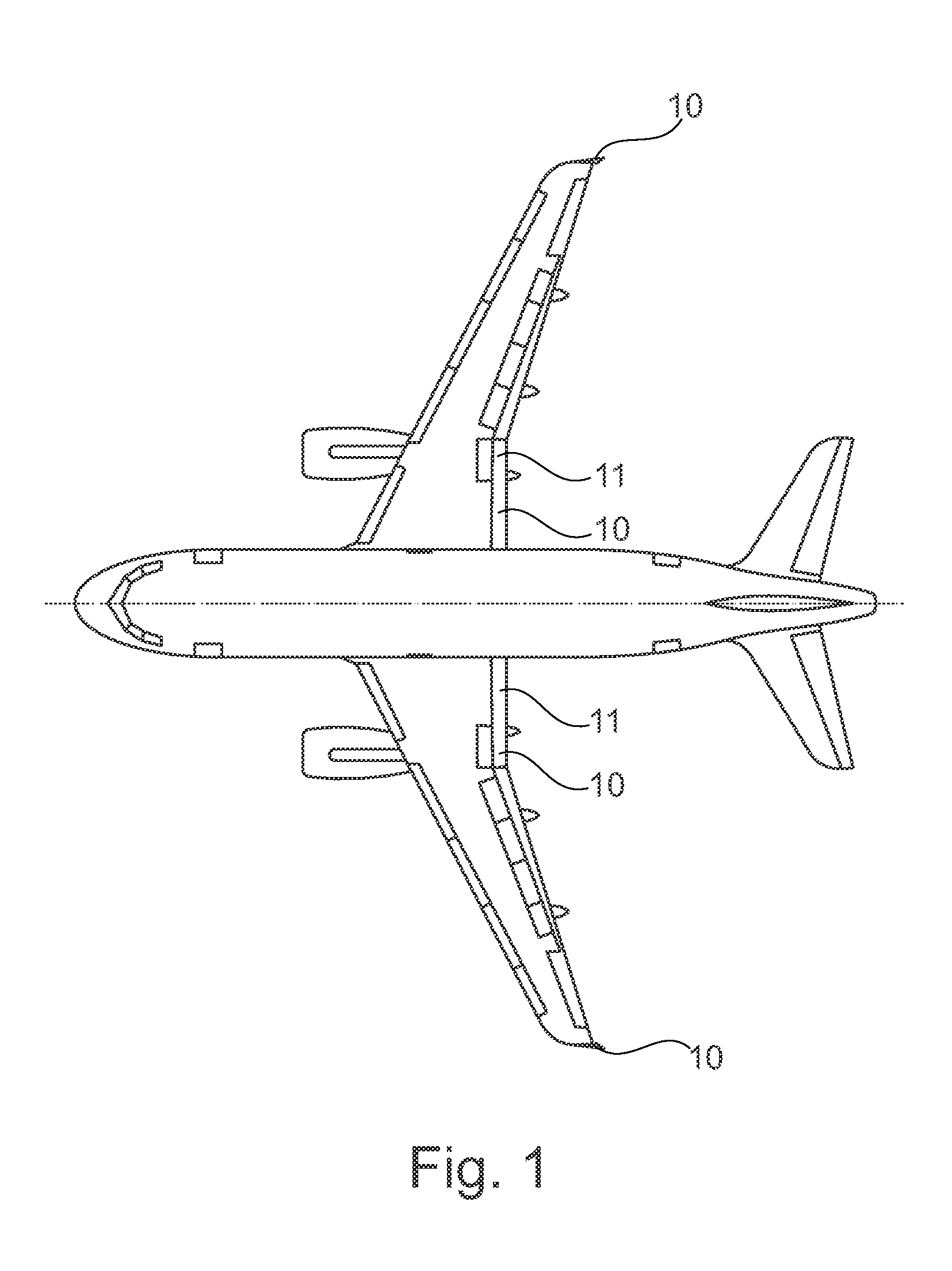
[0043]FIG. 1 shows schematically and exemplarily an embodiment of an aircraft 1 with a morphing airfoil 10 according to an embodiment of the invention. The aircraft 1 is here a plane. The morphing airfoil 10 is here shown to be a winglet and a flap 11 of the aircraft 1. The morphing airfoil 10 comprises a morphing trailing edge device (not shown), as will be explained in detail below. By morphing, a controlled and desired change of the shape of a part and / or an assembly without the creation of discontinuities such as gaps and kinks can be understood.

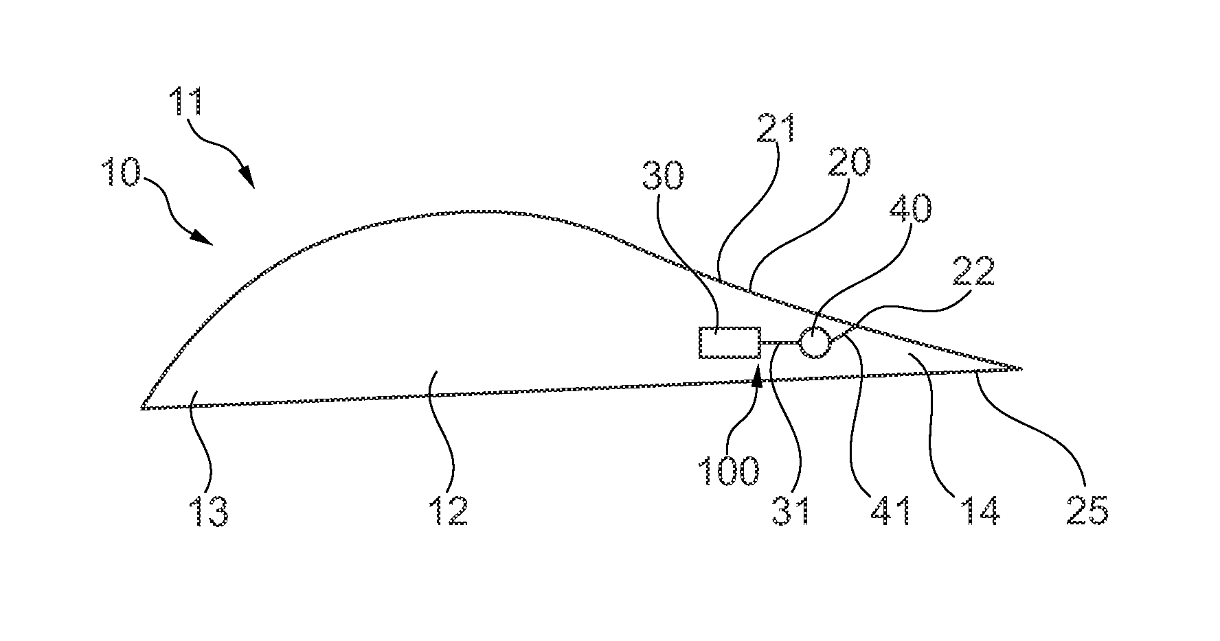
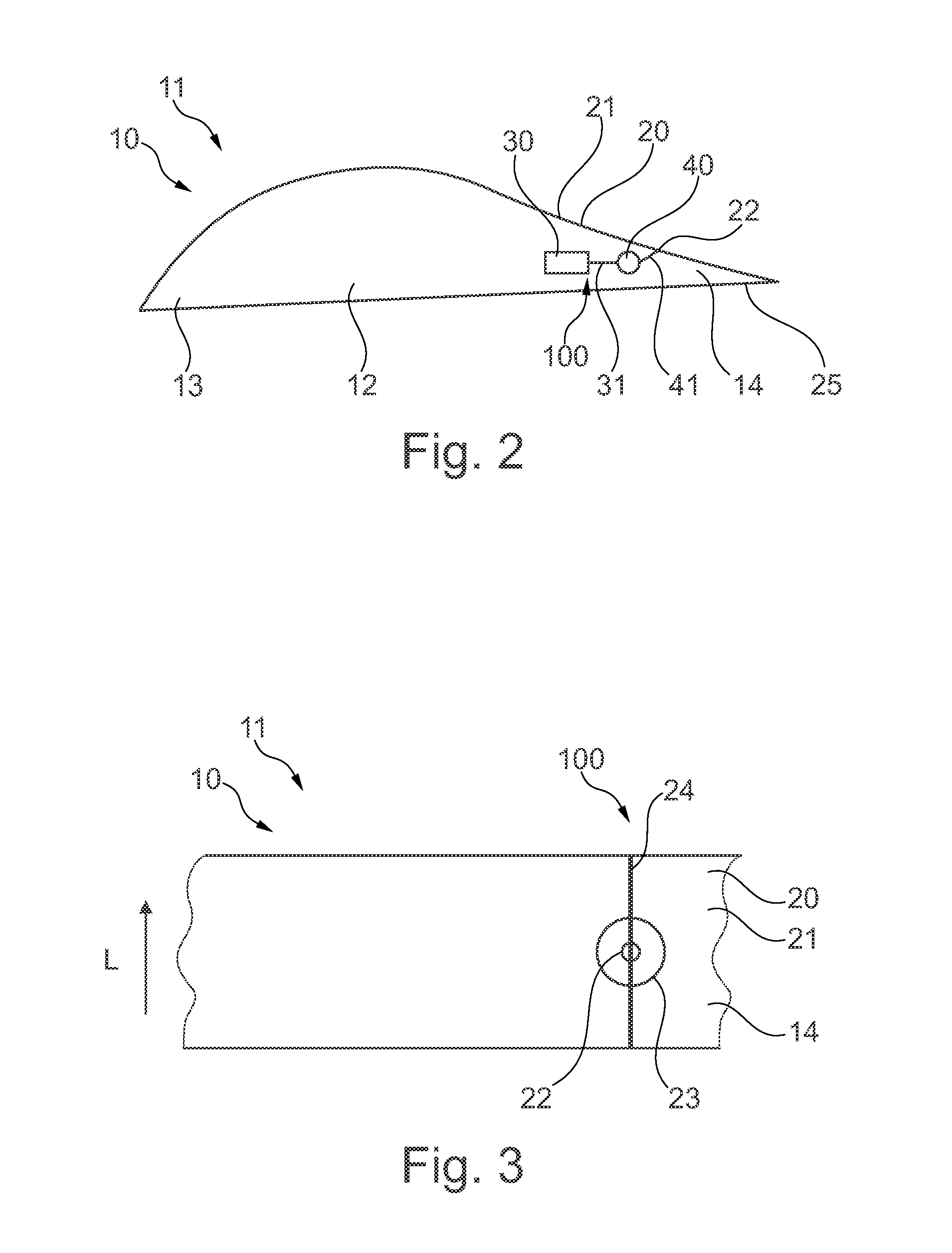
[0044]FIG. 2 shows schematically and exemplarily a cross section of the morphing airfoil 10 according to the invention, which is here a flap 11 of the aircraft 1. FIG. 3 shows schematically and exemplarily a part of the flap 11 shown in FIG. 2 as seen from above. The flap 11 comprises a torsion box 12 with a preceding leading edge region 13 and a trailing edge region 14 behind. The flap 11 further comprises the morphing trailing edge dev...


PUM

PropertyMeasurementUnit
Fractionaaaaaaaaaa
Fractionaaaaaaaaaa
Fractionaaaaaaaaaa

Abstract

A morphing trailing edge device for an airfoil includes a skin member, an actuator, and a torsion element. The skin member is configured to extend on a surface of a trailing edge region of an airfoil and includes a load introduction point within a reinforced area. The skin member further includes a stiffening member arranged essentially perpendicular to the load introduction point, wherein the load introduction point, the reinforced area and the stiffening member are integrated into the skin member. The actuator is configured to drive the torsion element with an actuation load. The torsion element is configured to translate the actuation load to the load introduction point, so that the actuation load morphs the trailing edge region up- or downwardly relative to a horizontal plane. A morphing airfoil for an aircraft, an aircraft with a morphing airfoil and a method for manufacturing a morphing airfoil are also described.

Description

FIELD OF THE INVENTION[0001]The invention relates to a morphing trailing edge device for an airfoil, a morphing airfoil for an aircraft, an aircraft with a morphing airfoil and a method for manufacturing a morphing airfoil for an aircraft.BACKGROUND OF THE INVENTION[0002]The design of conventional fixed wing aircraft provides an average performance over a range of mission segments, such as takeoff, cruise, dash, loiter, and landing; or optimal performance in the mission segment within which the most time is spent; and below average performance in other mission segments. Conventional mechanisms that result in geometric changes that enable operation over multiple mission segments, such as ailerons, elevators, rudders, spoilers, flaps and slats, are normally part of control systems that ensure the vehicle will be able to operate within a desired flight envelope, but the implementation of these systems does not typically result in a design that can continually respond and adapt to chang...

Claims


Application Information

Patent Timeline
IPC IPC(8): F01D5/14
CPCF01D5/141B64C3/48B64C2003/445
Inventor WÖLCKEN, PIET-CHRISTOF
Owner AIRBUS OPERATIONS GMBH
Why Eureka
Try Eureka