Puming system

a pumping system and pumping tube technology, applied in the direction of pump control, flexible member pump, positive displacement liquid engine, etc., can solve the problems of limiting the rate at which the bladder in each vessel is filled with water, reducing the efficiency of pumping, and reducing the cost of vessels to manufacture, so as to facilitate the assembly of the pumping apparatus and achieve the effect of smooth operation and equal

Inactive Publication Date: 2016-02-18
ERLS MINING
View PDF10 Cites 2 Cited by
  • Summary
  • Abstract
  • Description
  • Claims
  • Application Information

AI Technical Summary

Benefits of technology

[0049]As indicated, an equivalent and equally effective process can be implemented by replacing the water meters with the sensors. The sensors provide equivalent information to that generated by the water meters, namely an indication of when each bladder has been filled with slurry, an indication when each bladder has been emptied, and an indication of an intermediate position (e.g. that the bladder is half-full) at which suitable sequencing actions can be implemented to ensure a smooth operation.
[0050]Preferably, the supporting structure used for the pump units is in the nature of a conventional container. This substantially facilitates assembly of the pumping apparatus, its transport to a usage site and, at the usage site, installation and commissioning thereof. Site preparation requirements are minimised. Typically, at an installation site, the first and the second manifolds and the attendant one way and control valves, which are separately transported, e.g. in a second container, are connected to the pump units. The supporting structure (container) used for the pump units can have mounted to it gantries or jibs to facilitate assembly processes on site.

Problems solved by technology

The various functions in the second vessel, which are essential for effective pumping operation, are time consuming and place a limit on the rate at which the bladder in each vessel is filled with water i.e. the slurry pumping rate is restricted.
The vessels are expensive to manufacture.
The hemispherical ends are complex and costly to form and the nozzles, at the upper and lower ends, are forgings which are machined.
This is expensive and requires substantial production time.
The pump assemblies are large and, when transported, are regarded as abnormal loads and the relevant regulations then come into play.
In general a substantial amount of on-site work is required to install and commission the pumping system.

Method used


Image

  • Puming system
  • Puming system
  • Puming system

Examples


Embodiment Construction

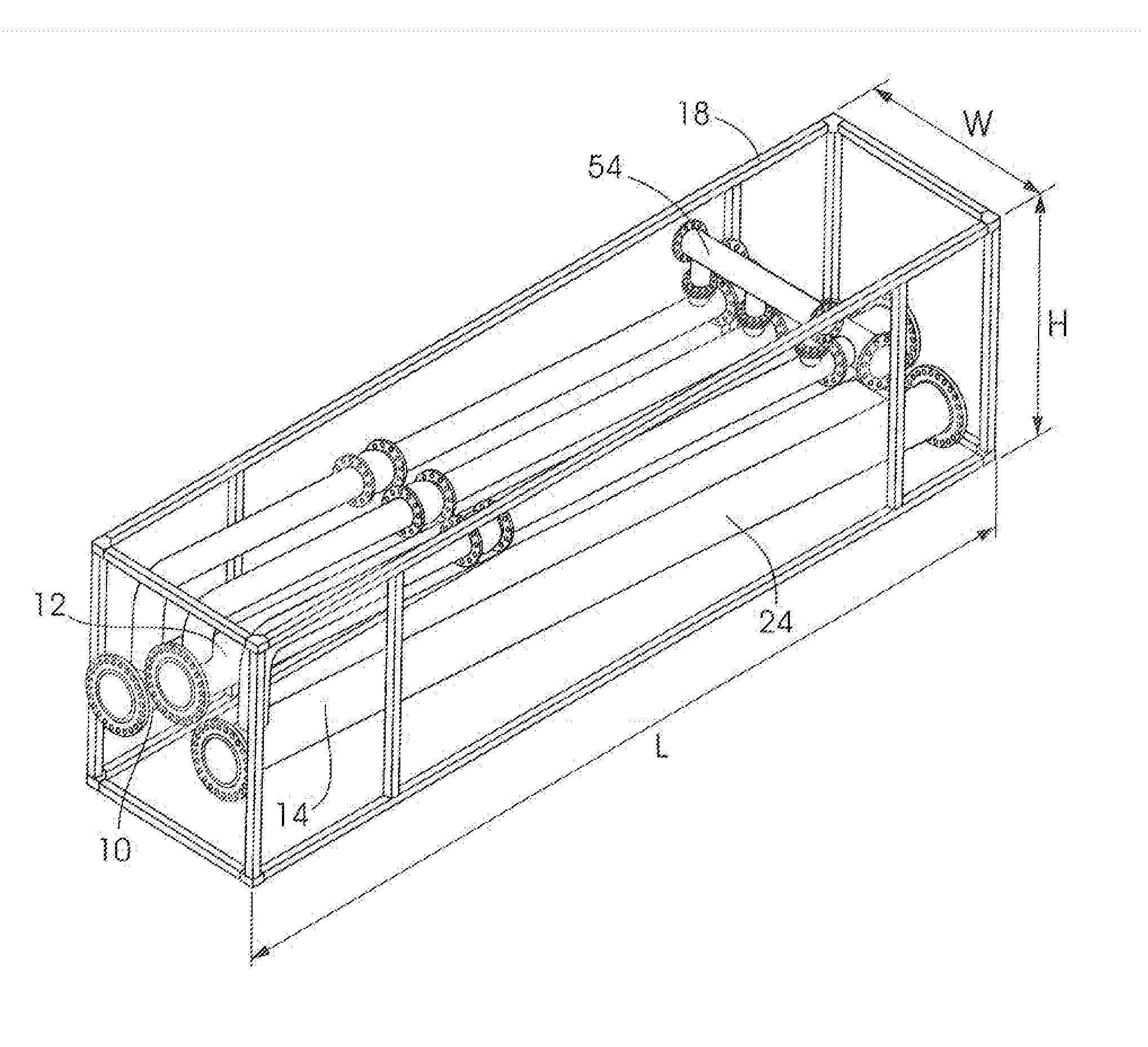
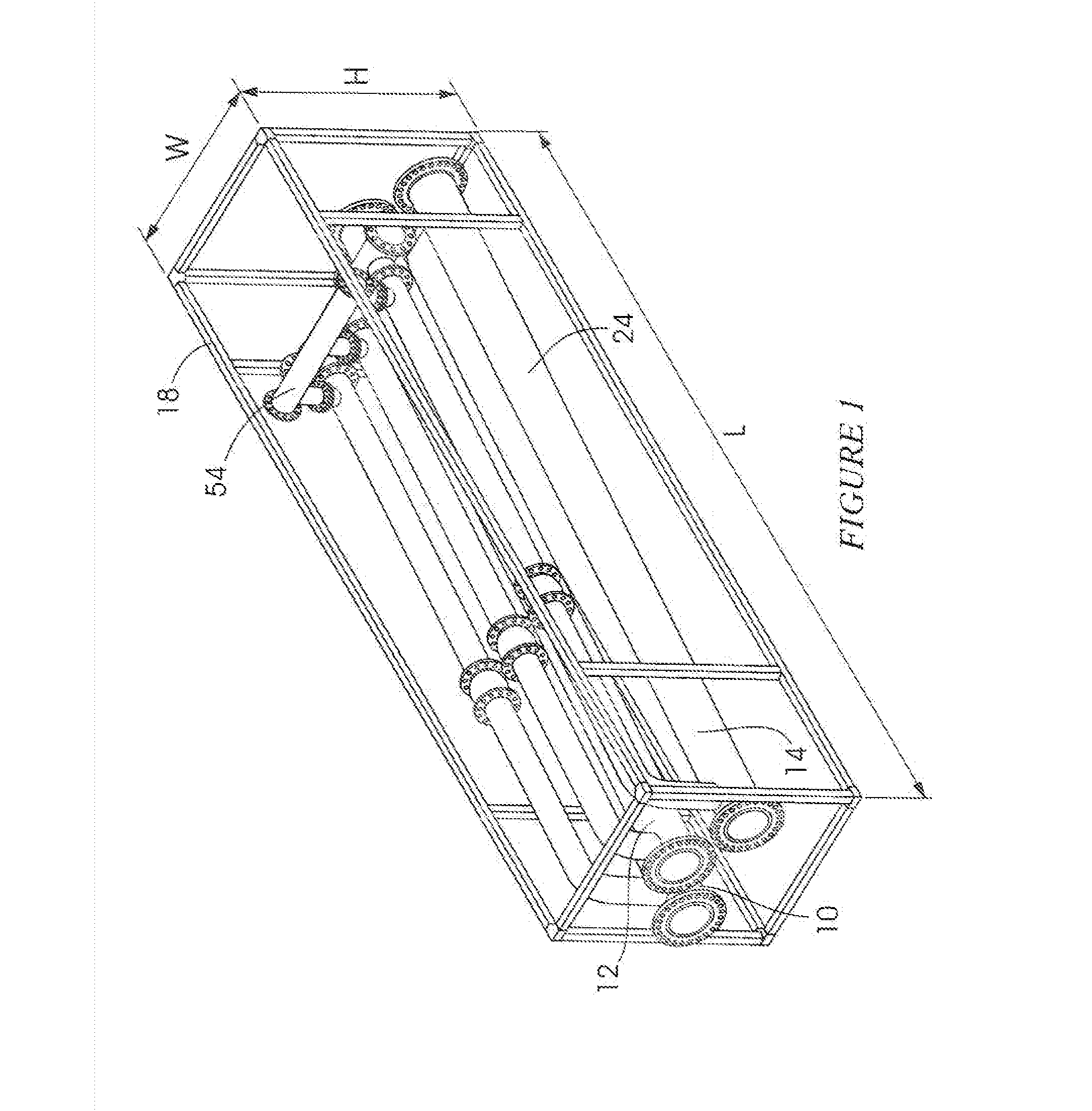
[0067]FIGS. 1 to 4 are different views of three pump units 10, 12 and 14 respectively which are mounted to supporting structure 18.

[0068]The supporting structure is shown in skeletal form. Typically the supporting structure is embodied in, or constituted by, a conventional transport container i.e. the structure 18 has a length L, a height H and a width W (FIG. 1) which conform to the dimensions of a conventional container. Sides of the supporting structure are not closed—this facilitates access to equipment mounted to the structure.

[0069]The construction of the unit 14 only is described hereinafter. The units 10 and 12 are similar to the unit 14.

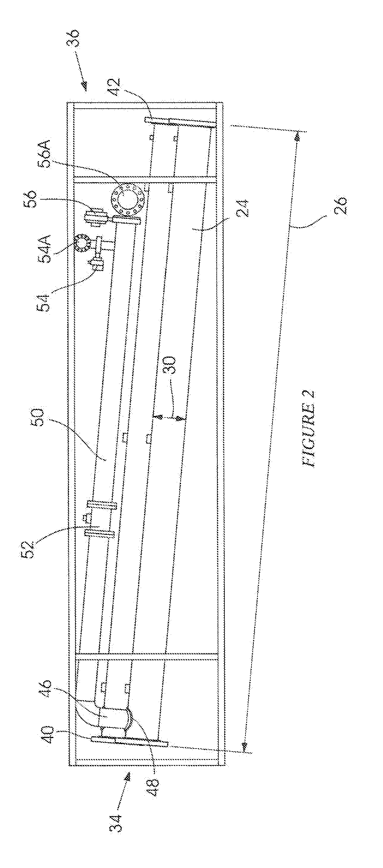
[0070]The unit 14 includes an elongate tubular housing 24 in the form of a pipe which is made to a suitable specification and which has a length 26 and a diameter 30. The pipe 24 has a first end 34 and an opposing second end 36. Each end is provided with a respective flange 40, 42.

[0071]Near the first end 34 (FIG. 2) the pipe 24 is formed wi...


PUM


Abstract

A pump unit which includes a pipe, a flexible bladder inside the pipe, an operating volume between an outer surface of the bladder and an opposing inner surface of the pipe, a valve arrangement to introduce pressurised water into the operating volume and to allow pressurised water to flow from the operating volume and another valve arrangement to allow slurry to flow into the interior of the bladder as water is expelled from the operating volume and to—allow slurry to flow from the bladder when water is introduced into the operating volume.

Description

BACKGROUND OF THE INVENTION[0001]This invention relates to pumping apparatus.[0002]The apparatus of the invention is suitable for pumping media such as slurries. The invention is described hereinafter with reference to this application, i.e. to the pumping of a slurry, but this is exemplary only and is non-limiting.[0003]The specification of international application No. PCT / ZA2009 / 000071 describes a pumping system which makes use of two pressure vessels. Each vessel is cylindrical with hemispherical ends and is orientated so that its longitudinal axis is vertical. Nozzles are provided at upper and lower ends of the vessel.[0004]Each vessel contains an elongate flexible bladder which is aligned with the longitudinal axis. The bladder, at an upper end, has an open neck which is sealingly engaged with the upper nozzle to define a first volume within the bladder and a second volume between the bladder and an opposing inner surface of the wall of the vessel.[0005]Slurry is fed gravitati...

Claims


Application Information

Patent Timeline
Patent Type & Authority Applications(United States)
IPC IPC(8): F04B43/113F04B15/02
CPCF04B15/02F04B43/113F04B43/1136
Inventor WOOD, RICHARD ROYBREDIN, MURRAY
Owner ERLS MINING
Why Eureka
Try Eureka