
Ventilator

a technology of ventilator and air intake, which is applied in the field of ventilator, can solve the problems of increasing the breathing work of patients, and achieve the effect of equal efficiency

Inactive Publication Date: 2012-03-08
LIFEVENT MEDICAL LTD
View PDF3 Cites 1 Cited by
  • Summary
  • Abstract
  • Description
  • Claims
  • Application Information

AI Technical Summary

Benefits of technology

"The present invention provides a ventilator that can provide a range of different modes of ventilation, such as CPAP, ASB, MV, HFOV, or any combination of these modes, without requiring major reconfiguration of the ventilator when switching between different modes. The ventilator includes at least one pair of reciprocating opposed gas moving means, which are arranged to move gas at a predetermined pressure and / or volume to a delivery tube. The gas moving means are balanced to minimize the vibration of the ventilator in use. The balanced drive is a linear or rotary balanced drive that is capable of a fast response to the control means. The gas moving means may be any suitable receptacle, such as bellows or cylinders and pistons. The balanced drive is mounted upon rails and is arranged to move upon rails when reciprocating. The mass of the balanced drive is minimized to minimize vibration of the ventilator in operation. The gas moving means may comprise cylinders and pistons, and the balanced drive includes a stator and a slider that produce an equal but opposite movement of each other. The ventilator can be used in combination with a conventional ventilator to superimpose HFOV on conventional ventilation. The present invention also provides a ventilation delivery system that includes the ventilator, a gas supply, a gas delivery hose, and patient gas delivery means."

Problems solved by technology

When a patient takes a spontaneous breath the ventilator must synchronise with the patient's breathing cycle and it follows that the ventilator must be able to sense demand and delivery accurately, because any failure to synchronise accurately with the patient will both increase the breathing work for the patient and cause discomfort.

Method used


Image

  • Ventilator
  • Ventilator
  • Ventilator

Examples


first embodiment

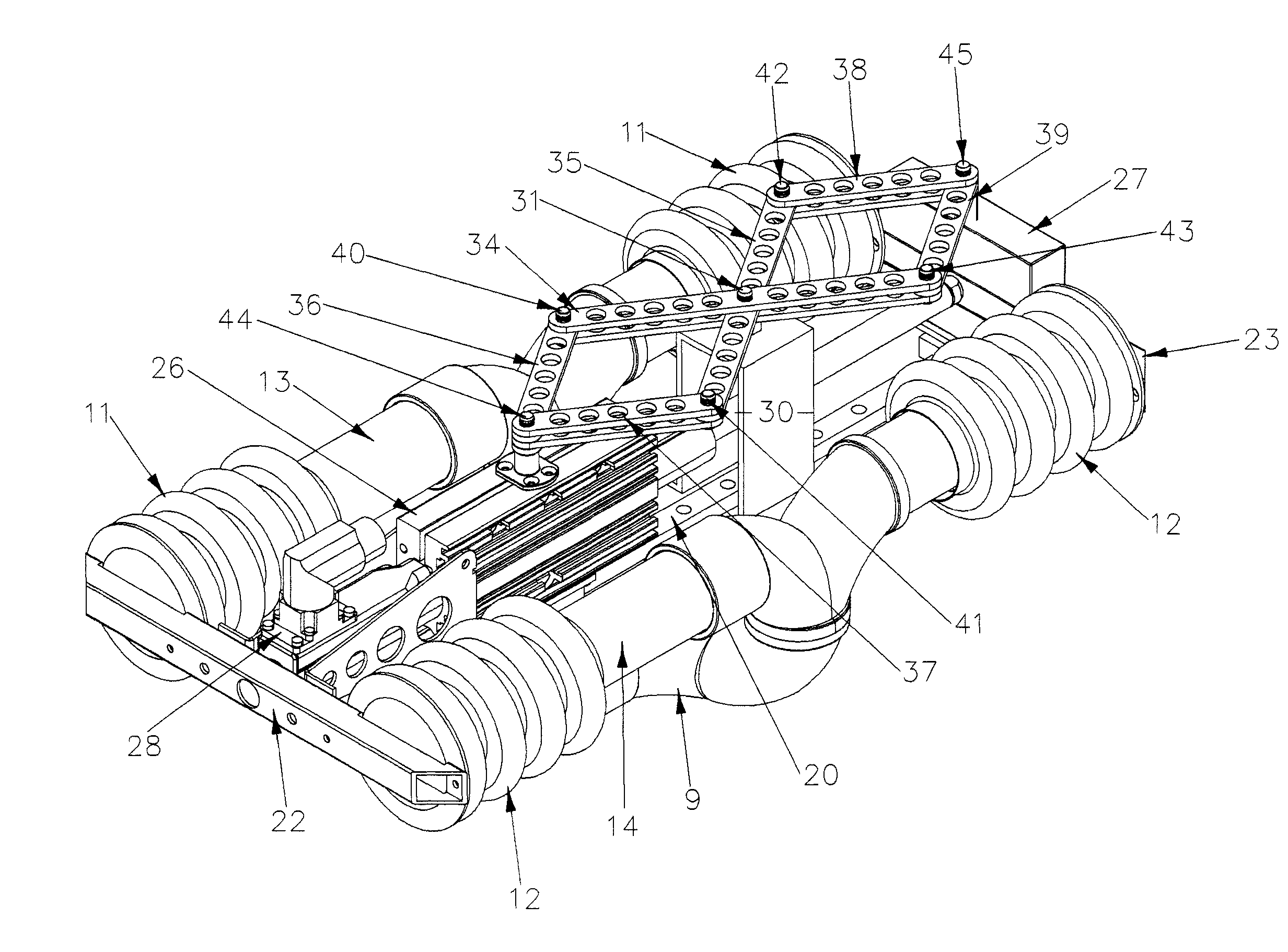
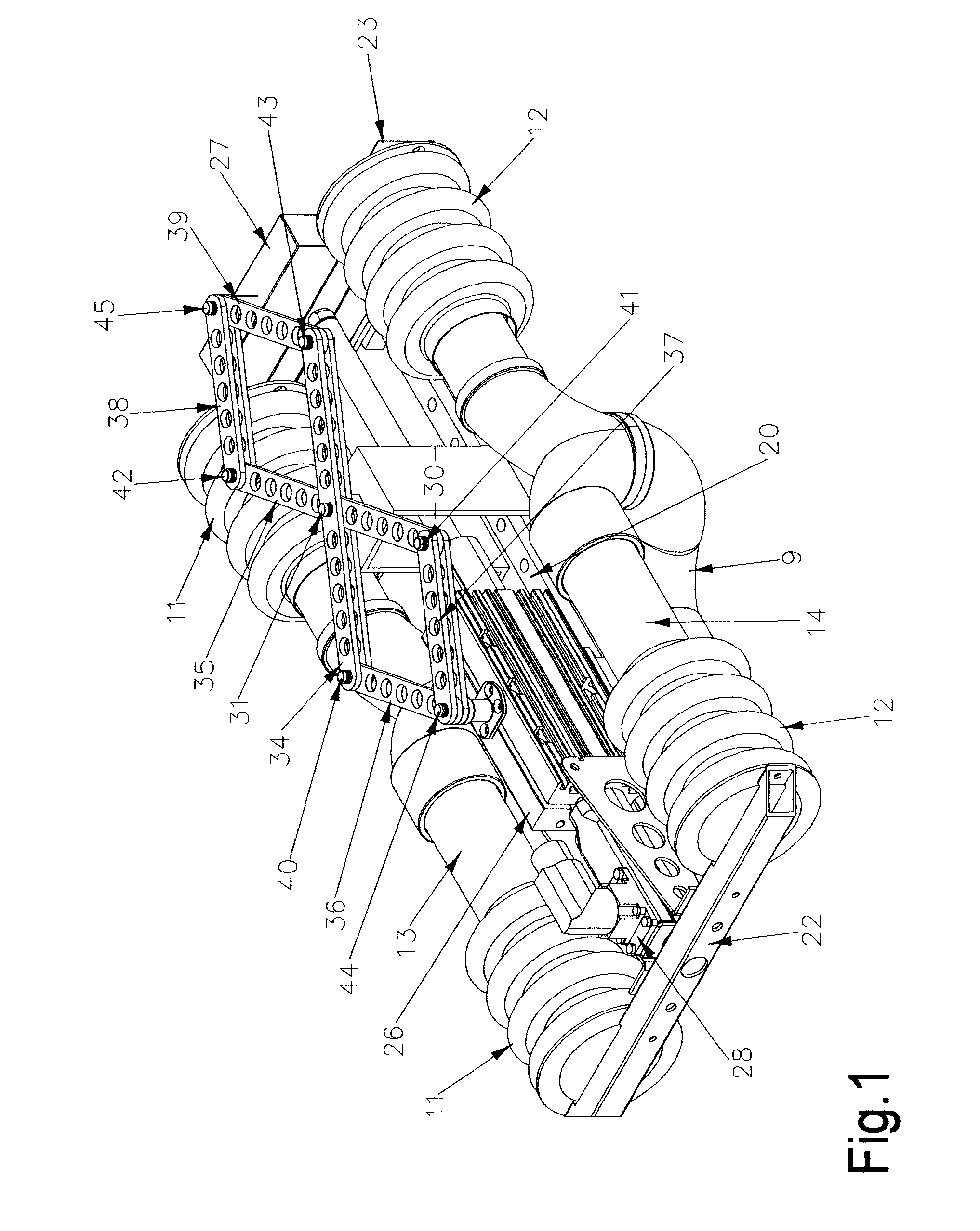
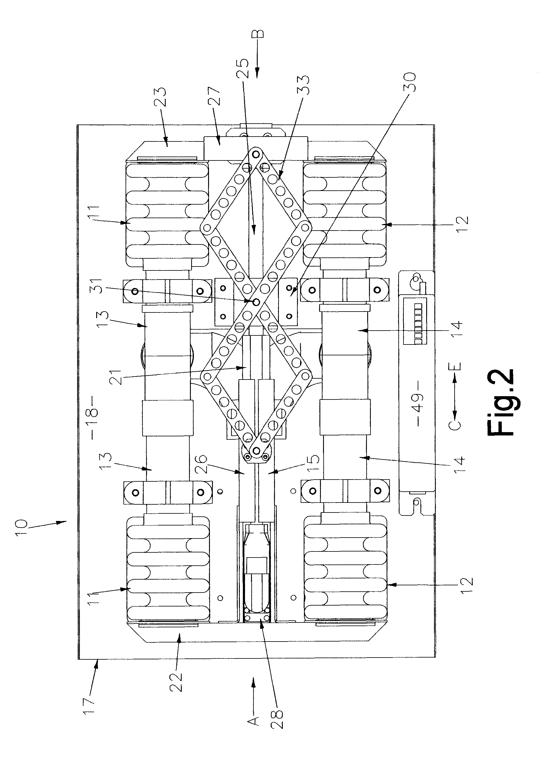
[0037]Referring to FIGS. 1 to 4 of the drawings, a ventilator 10 in accordance with the present invention includes two pairs of opposed gas moving means in the form of bellows 11,12, each bellow of each pair of bellows being connected at one end to an outlet tube 13,14 which join into a common outlet 9. The bellows pairs 11,12 are spaced apart and a linear motor 15 is mounted between the pairs of bellows. As used herein, the term “linear motor” means a linear induction motor. Any suitable linear motor in the known range of linear induction motors may be used; this may include a pair of linear motors, each acting on one opposing set of bellows such that there is minimal net movement of the apparatus. Linear motors are electronically powered.

[0038]The bellows 11,12 and the linear motor 15 are mounted upon a base 17 which, as shown particularly in FIGS. 3 and 4, provides a flat supporting surface 18 which is rectangular in shape, and has a supporting foot 19 at each corner. The other s...

third embodiment

[0058]FIGS. 10 to 13 show the present invention, in which the linear motor 15 is replaced by a pneumatic or hydraulic ram 101. The embodiment shown in FIGS. 10 to 13 is identical to that described with reference to FIGS. 6 to 9 except for the substitution of the linear motor 15 by a pneumatic or hydraulic ram 101, and therefore only this feature will be described in detail; the same reference numerals as in FIGS. 6 to 9 are used where the components are the same.

[0059]The pneumatic or hydraulic ram 101 may be of any suitable known type and consists, in known manner, of a cylinder containing a piston mounted on a piston rod; the cylinder is fitted with pneumatic / hydraulic inlets and outlets in known manner; these are not shown in the drawings for reasons of clarity. The ram 101 is mounted on the rails 20 and is surrounded by cooling fins 102 to which brackets 60, 61 are attached to form a load transmitting connection between the ram 101, the cooling fins 102, the connecting rods 57, ...


PUM


Abstract

A ventilator which includes: at least one pair of reciprocating opposed gas moving means, the internal volume of which is arranged to be reduced and enlarged by a balanced drive, said gas moving means being arranged to move gas at a predetermined pressure and / or volume to a delivery tube; control means for regulating the speed and the distance of movement of the drive; wherein the masses of all moving parts are balanced so as to minimise the vibration of the ventilator in use.

Description

TECHNICAL FIELD [0001]The present invention relates to a ventilator which is capable of providing, continuous positive airway pressure (CPAP), assisted spontaneous breathing (ASB), all forms of mandatory ventilation (MV), and high frequency ventilation (HFV). All of these ventilation modes are known.[0002]CPAP typically supplies gas at a pressure in the range 2.5 cm water to 15 cm water, at a frequency controlled by the patient and typically in the range 8 to 30 breaths per minute.[0003]ASB typically supplies gas at a pressure in the range 5 cm water to 15 cm water above the expired pressure (which is typically 2.5 cm water to 15 cm water), with the frequency controlled by the patient as for CPAP; typical volumes for ASB are in the range 6 to 10 mL per kilogram of predicted patient weight. ASB may include, but is not limited to, the following modes of ventilation: bilevel, airway pressure release, proportional assist, pressure support, or volume assured ventilation.[0004]Mandatory v...

Claims


Application Information

Patent Timeline
Patent Type & Authority Applications(United States)
IPC IPC(8): A61M16/00A61M16/04F04B49/20A61M16/06
CPCA61M16/0075A61M16/0072A61M2016/0036A61M2016/0027A61M16/107
Inventor SHAW, GEOFFREY MARKANDERS, GEOFFREYALLOO, LAWRENCE GORDON
Owner LIFEVENT MEDICAL LTD
Learn More