Solar receiver, particularly of the type for parabolic linear solar concentrators and the like

a solar concentrator and receiver technology, applied in the field of solar receivers, can solve the problems of mainly efficiency loss, increase in heat loss at the tube during the operation of the concentrator, etc., and achieve the effect of maintaining durably the thermal insulation efficiency of hea

Inactive Publication Date: 2016-04-26
RONDA HIGH TECH
View PDF46 Cites 0 Cited by
  • Summary
  • Abstract
  • Description
  • Claims
  • Application Information

AI Technical Summary

Benefits of technology

[0020]Within this aim, an object of the invention is to propose a solar receiver that makes it possible to achieve higher operating temperatures than those of currently known receivers for an equal efficiency.
[0023]Another object of the invention is to provide a solar receiver that makes it possible to maintain durably the thermal insulation efficiency of the heat transfer fluid that flows into it during use.
[0024]Another object of the invention is to propose a solar receiver that makes it possible to avoid failures of the articulated joints that connect the circulation tube of the heat transfer fluid and the delivery and discharge ducts and are adapted to allow the joint rotation of the mirror and of the tube that is joined integrally to it.

Problems solved by technology

As is known, the heat loss that occurs at the tube during the operation of the concentrator increases as the temperature of the tube rises.
The efficiency losses that occur when using this second solution with respect to the first one are mainly due to the heat dissipations located at the receiver.

Method used


Image

  • Solar receiver, particularly of the type for parabolic linear solar concentrators and the like
  • Solar receiver, particularly of the type for parabolic linear solar concentrators and the like
  • Solar receiver, particularly of the type for parabolic linear solar concentrators and the like

Examples


Embodiment Construction

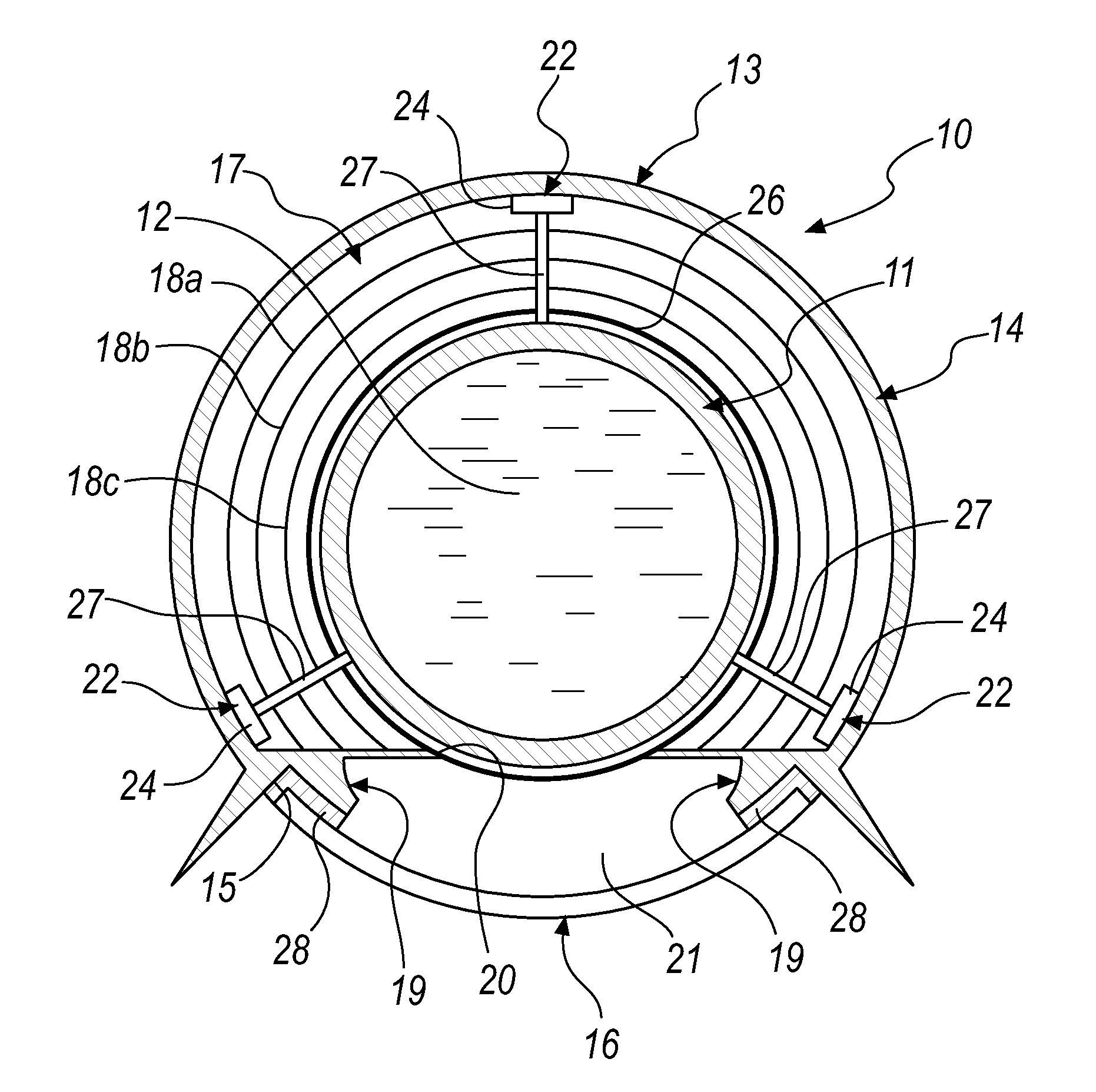
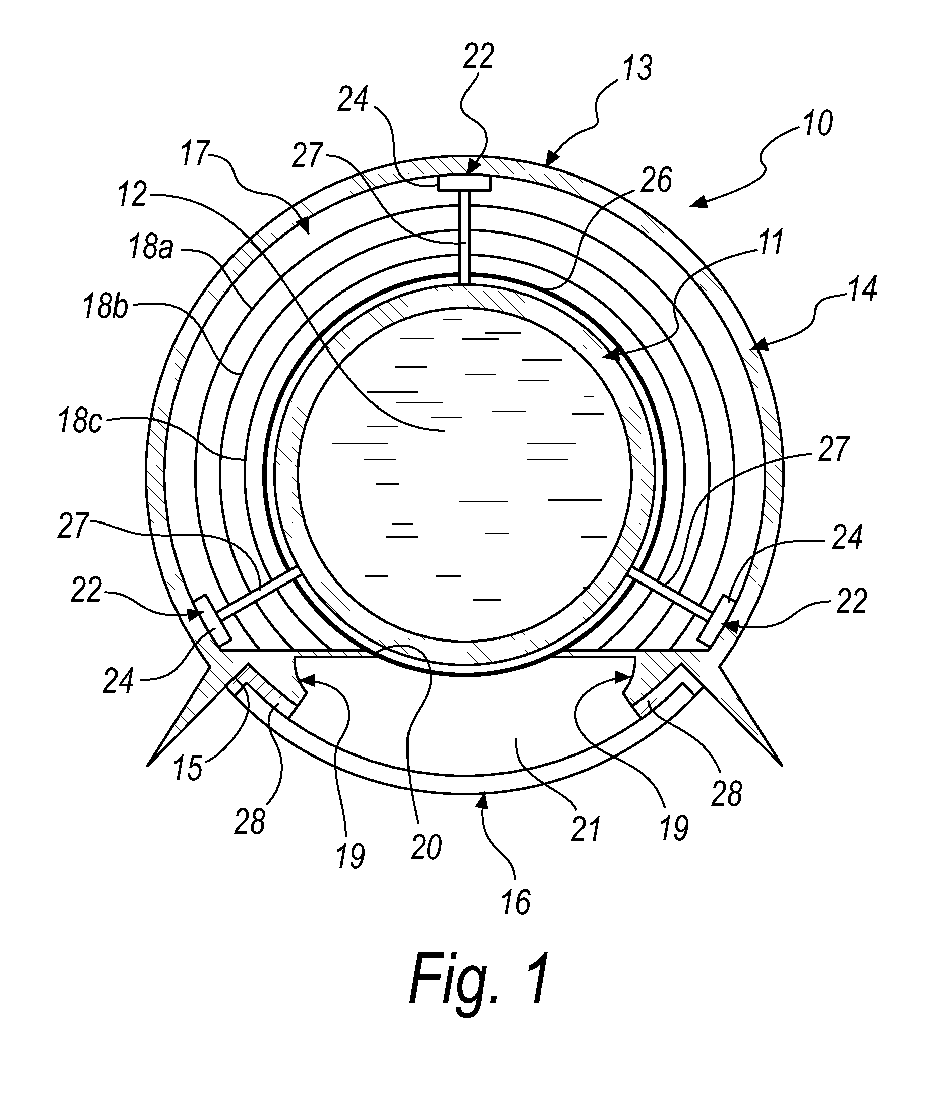
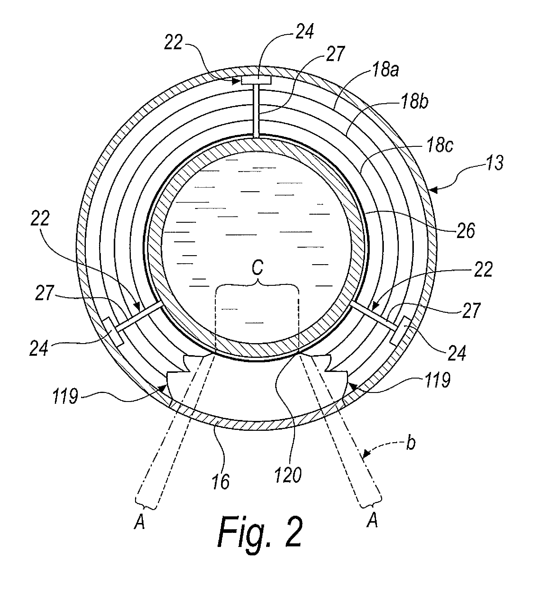
[0033]With reference to the figures, the numeral 10 generally designates a solar receiver, particularly of the type for parabolic linear solar concentrators and the like, which according to the invention comprises a receiver tube 11, for the circulation of a heat transfer fluid 12, which is supported in a longitudinally adaptable manner in a shell 13 that comprises[0034]a shielding body 14 provided with a longitudinal slit 15, and[0035]a lens 16 for closing the slit 15, which is permeable to the solar radiation that is reflected toward the receiver tube 11 by a concentrator mirror with which the shell 13 is associated during use.

[0036]Furthermore, according to the invention, an annular chamber 17 is provided between the receiver tube 11 and the shell 13 and contains a preselected thermally insulating gas at an operating pressure substantially comprised between 1 mbar and 31 mbar and preferably substantially equal to 10 mbar, the preselected gas having, at such operating pressure, a ...


PUM


Abstract

A solar receiver, particularly of the type for parabolic linear solar concentrators comprising a receiver tube, for the circulation of a heat transfer fluid, which is supported in a longitudinally adaptable manner in a shell that comprises a shielding body provided with a longitudinal slit, and at least one lens for closing the slit, which is permeable to the solar radiation that during use is reflected toward the receiver tube by a concentrator mirror, with which the shell is associated during use. Between the receiver tube and the shell an annular chamber is provided, which contains a preselected thermally insulating gas, at an operating pressure substantially comprised between 1 mbar and 31 mbar, the preselected gas having a thermal conductivity of substantially less than 0.01 W / mK at the operating temperature at the operating pressure.

Description

CROSS-REFERENCE TO RELATED APPLICATIONS[0001]This application is a National Phase Application of PCT International Application No. PCT / IB2011 / 051413, International Filing Date Apr. 1, 2011, claiming priority of Italian Patent Application No. PD2010A000106, filed Apr. 2, 2010, which is hereby incorporated by reference.TECHNICAL FIELD[0002]The present invention relates to a solar receiver, particularly of the type for parabolic linear solar concentrators and the like.BACKGROUND ART[0003]Receivers for solar concentrators currently have a metallic tube into which the heat transfer fluid flows; the concentrator mirror reflects solar radiation, concentrating it on the tube, in which the fluid is heated in order to be used as a heat source for industrial processes or for the generation of electric power in a thermodynamic-cycle plant, optionally of the combined-cycle type for the combined generation of electric power and thermal power.[0004]One strongly felt need in the field of solar conc...

Claims


Application Information

Patent Timeline
Patent Type & Authority Patents(United States)
IPC IPC(8): F24J2/08F24J2/07F24J2/46F24J2/14F24J2/24F24J2/12F24J2/10F24S10/70F24S20/20F24S23/30F24S23/70F24S23/71F24S23/74
CPCF24J2/07F24J2/4636F24J2/08F24J2/14Y02E10/41F24S20/20F24S23/30F24S23/74F24S40/80Y02E10/40
Inventor SIMONETTI, TANCREDISALINARI, PIERORONDA, GIOVANNI
Owner RONDA HIGH TECH
Why Eureka
Try Eureka